Cisco 2950 Hardware Installation Guide - Page 108
Adapter Pinouts, Function, Console, Port DTE, RJ-45-to-DB-9, Adapter Cable, Device, Signal, RJ-45 Pin
 |
UPC - 746320454504
View all Cisco 2950 manuals
Add to My Manuals
Save this manual to your list of manuals |
Page 108 highlights
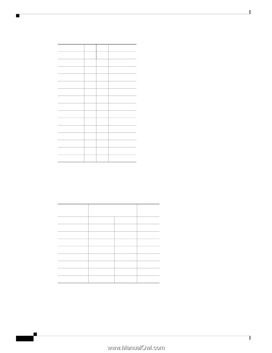
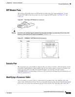
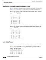
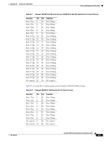
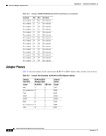
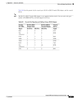
Cable and Adapter Specifications Appendix B Connectors and Cables Table B-2 Catalyst 2950ST-8 LRE Switch RJ-21 Cable Pinouts (continued) Function Pin Pin Function No connect 11 36 No connect No connect 12 37 No connect No connect 13 38 No connect No connect 14 39 No connect No connect 15 40 No connect No connect 16 41 No connect No connect 17 42 No connect No connect 18 43 No connect No connect 19 44 No connect No connect 20 45 No connect No connect 21 46 No connect No connect 22 47 No connect No connect 23 48 No connect No connect 24 49 No connect No connect 25 50 No connect Adapter Pinouts Table B-3 lists the pinouts for the console port, the RJ-45-to-DB-9 adapter cable, and the console device. Table B-3 Console Port Signaling and RJ-45-to-DB-9 Adapter Cabling Console Port (DTE) RJ-45-to-DB-9 Adapter Cable Signal RJ-45 Pin DB-9 Pin RTS 1 8 Not connected 2 6 TxD 3 2 GND 4 5 GND 5 5 RxD 6 3 Not connected 7 4 CTS 8 7 Console Device Signal CTS DSR RxD GND GND TxD DTR RTS B-10 Catalyst 2950 Switch Hardware Installation Guide OL-6156-01
-
 1
1 -
2
-
3
-
4
-
5
-
6
-
7
-
8
-
9
-
10
-
11
-
12
-
13
-
14
-
15
-
16
-
17
-
18
-
19
-
20
-
21
-
22
-
23
-
24
-
25
-
26
-
27
-
28
-
29
-
30
-
31
-
32
-
33
-
34
-
35
-
36
-
37
-
38
-
39
-
40
-
41
-
42
-
43
-
44
-
45
-
46
-
47
-
48
-
49
-
50
-
51
-
52
-
53
-
54
-
55
-
56
-
57
-
58
-
59
-
60
-
61
-
62
-
63
-
64
-
65
-
66
-
67
-
68
-
69
-
70
-
71
-
72
-
73
-
74
-
75
-
76
-
77
-
78
-
79
-
80
-
81
-
82
-
83
-
84
-
85
-
86
-
87
-
88
-
89
-
90
-
91
-
92
-
93
-
94
-
95
-
96
-
97
-
98
-
99
-
100
-
101
-
102
-
 103
103 -
 104
104 -
 105
105 -
 106
106 -
 107
107 -
 108
108 -
 109
109 -
 110
110 -
 111
111 -
 112
112 -
 113
113 -
114
-
115
-
116
-
117
-
118
-
119
-
120
-
121
-
122
-
123
-
124
-
125
-
126
-
127
-
128
-
129
-
130
-
131
-
132
-
133
-
134
 |
 |