Cisco 2950 Hardware Installation Guide - Page 80
Connecting to an LRE Port on a Catalyst 2950ST-24 LRE 997 Switch
 |
UPC - 746320454504
View all Cisco 2950 manuals
Add to My Manuals
Save this manual to your list of manuals |
Page 80 highlights
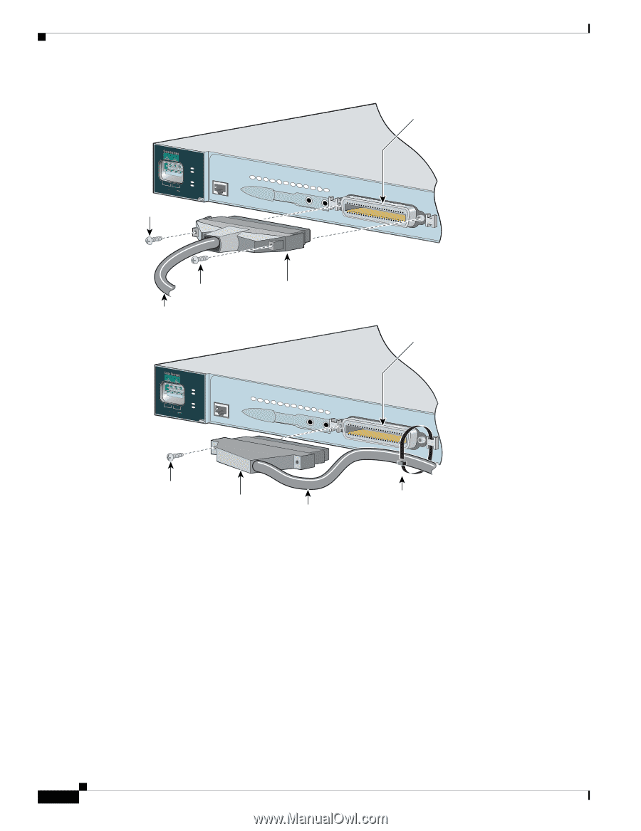
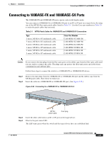
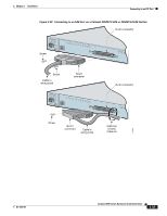
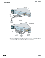
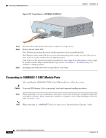
Connecting to an LRE Port Chapter 2 Installation Figure 2-39 Connecting to an LRE Port on a Catalyst 2950ST-24 LRE 997 Switch RJ-21 connector ++ A INPCUUTR:RE3N6T- B 72 V :2-1 A Screw SYST RPS STAT SPEED MODE CONSOLE 1 2 3 4 5 6 7 8 9 10 11 12 --- Screw Cable to wiring trunk RJ-21 connector ++ A INPCUUTR:RE3N6T- B 72 V :2-1 A SYST RPS STAT SPEED MODE CONSOLE 1 2 3 4 5 6 7 8 9 10 11 12 RJ-21 connector Screw RJ-21 connector Cable to wiring trunk 0.20 inch (5 mm) Cable tie 89366 Each LRE port status LED turns on when it establishes a link with a Cisco LRE CPE device. For more information about the LRE link between the switch LRE port and the CPE and about the configuration and management of CPE devices, see the switch software configuration guide. For more information about the Cisco LRE CPE devices, see the Cisco LRE CPE Hardware Installation Guide. 2-34 Catalyst 2950 Switch Hardware Installation Guide OL-6156-01
-
 1
1 -
2
-
3
-
4
-
5
-
6
-
7
-
8
-
9
-
10
-
11
-
12
-
13
-
14
-
15
-
16
-
17
-
18
-
19
-
20
-
21
-
22
-
23
-
24
-
25
-
26
-
27
-
28
-
29
-
30
-
31
-
32
-
33
-
34
-
35
-
36
-
37
-
38
-
39
-
40
-
41
-
42
-
43
-
44
-
45
-
46
-
47
-
48
-
49
-
50
-
51
-
52
-
53
-
54
-
55
-
56
-
57
-
58
-
59
-
60
-
61
-
62
-
63
-
64
-
65
-
66
-
67
-
68
-
69
-
70
-
71
-
72
-
73
-
74
-
 75
75 -
 76
76 -
 77
77 -
 78
78 -
 79
79 -
 80
80 -
 81
81 -
 82
82 -
 83
83 -
 84
84 -
 85
85 -
86
-
87
-
88
-
89
-
90
-
91
-
92
-
93
-
94
-
95
-
96
-
97
-
98
-
99
-
100
-
101
-
102
-
103
-
104
-
105
-
106
-
107
-
108
-
109
-
110
-
111
-
112
-
113
-
114
-
115
-
116
-
117
-
118
-
119
-
120
-
121
-
122
-
123
-
124
-
125
-
126
-
127
-
128
-
129
-
130
-
131
-
132
-
133
-
134
 |
 |