Cisco 2950 Hardware Installation Guide - Page 111
Connecting to DC Power
 |
UPC - 746320454504
View all Cisco 2950 manuals
Add to My Manuals
Save this manual to your list of manuals |
Page 111 highlights
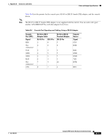
C A P P E N D I X Connecting to DC Power To connect the Catalyst 2950G-24-EI-DC or Catalyst 2950ST-24 LRE 997 switch to a direct current (DC)-input power source, follow these steps: 1. Preparing for Installation, page C-2 2. Grounding the Switch, page C-2 3. Wiring the DC-Input Power Source, page C-4 Warning The Catalyst 2950G-24-EI-DC contains no field-replaceable units (FRUs). Do not open the chassis or attempt to remove or replace any components. For information about obtaining service for this unit, contact your reseller or Cisco sales representative. Statement 121C Warning The Catalyst 2950ST-24 LRE 997 contains no field-replaceable units (FRUs). Do not open the chassis or attempt to remove or replace any components. For information about obtaining service for this unit, contact your reseller or Cisco sales representative. Statement 121D Warning This unit is intended for installation in restricted access areas. A restricted access area can be accessed only through the use of a special tool, lock and key, or other means of security. Statement 1017 Warning Ethernet cables must be shielded when used in a central office environment. Statement 171 Caution Installation of the equipment must comply with local and national electrical codes. OL-6156-01 Catalyst 2950 Switch Hardware Installation Guide C-1
-
 1
1 -
2
-
3
-
4
-
5
-
6
-
7
-
8
-
9
-
10
-
11
-
12
-
13
-
14
-
15
-
16
-
17
-
18
-
19
-
20
-
21
-
22
-
23
-
24
-
25
-
26
-
27
-
28
-
29
-
30
-
31
-
32
-
33
-
34
-
35
-
36
-
37
-
38
-
39
-
40
-
41
-
42
-
43
-
44
-
45
-
46
-
47
-
48
-
49
-
50
-
51
-
52
-
53
-
54
-
55
-
56
-
57
-
58
-
59
-
60
-
61
-
62
-
63
-
64
-
65
-
66
-
67
-
68
-
69
-
70
-
71
-
72
-
73
-
74
-
75
-
76
-
77
-
78
-
79
-
80
-
81
-
82
-
83
-
84
-
85
-
86
-
87
-
88
-
89
-
90
-
91
-
92
-
93
-
94
-
95
-
96
-
97
-
98
-
99
-
100
-
101
-
102
-
103
-
104
-
105
-
 106
106 -
 107
107 -
 108
108 -
 109
109 -
 110
110 -
 111
111 -
 112
112 -
 113
113 -
 114
114 -
 115
115 -
 116
116 -
117
-
118
-
119
-
120
-
121
-
122
-
123
-
124
-
125
-
126
-
127
-
128
-
129
-
130
-
131
-
132
-
133
-
134
 |
 |