Cisco 2950 Hardware Installation Guide - Page 31
SFP Module Slots, SFP Modules
 |
UPC - 746320454504
View all Cisco 2950 manuals
Add to My Manuals
Save this manual to your list of manuals |
Page 31 highlights
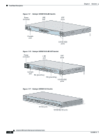
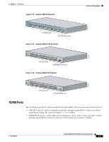
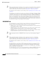
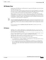
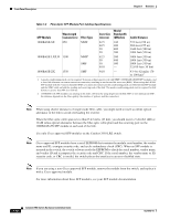
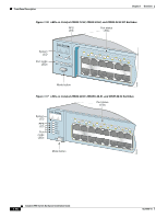
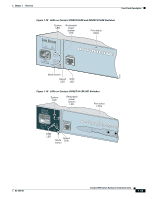
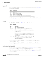
Chapter 1 Overview Front-Panel Description SFP Module Slots On the Catalyst 2950 LRE switch, the SFP module slots support the SFP modules listed in the Catalyst 2950 LRE switch release notes. The Catalyst 2950 LRE switch has four physical input ports that are logically bundled as two ports. Each logical port consists of a copper 10/100/1000 port and a fiber-optic SFP module slot. These ports appear as a vertical column on the front panel and are labeled Uplink Port 1 and Uplink Port 2. Within each port, you can use only one of the two physical ports, either the SFP module port or the 10/100/1000 port. For example, you can connect to either the SFP module port or the 10/100/1000 port on Uplink Port 1. If you connect to both, in default operation, the SFP module port has priority over the 10/100/1000 port. Using this example, a valid configuration would be connecting to the fiber-optic port on Uplink Port 1 and the copper port on Uplink Port 2. Note By using the media-type {sfp | rj45 | auto-select} interface configuration command at the CLI, you can configure the Catalyst 2950 LRE switch so that the SFP module port does not take precedence over the 10/100/1000 port. In that scenario, whichever media type establishes a link first has precedence over the other. For more information about the media-type {sfp | rj45 | auto-select} command, see the switch command reference. SFP Modules The LRE switches use Ethernet SFP modules to establish uplink connections to other devices. The SFP modules are inserted into SFP module slots on the front of the Catalyst 2950 LRE switches. These transceiver modules are field-replaceable. You use fiber-optic cables with LC or MT-RJ connectors to connect to fiber-optic SFP modules. You use Category 5 cable with RJ-45 connectors to connect to 1000BASE-T SFP modules. The SFP modules support nominal wavelengths from 850 to 1550 nanometers (nm). See the Catalyst 2950 LRE switch release notes for the list of supported SFP modules. When determining where to place the switch, be sure to observe these requirements: • For 10/100/1000 ports, including 1000BASE-T SFP module ports, cable lengths from the switch to connected devices are up to 328 feet (100 meters). • Table 1-2 lists the cable specifications for 1000BASE-SX, 1000BASE-LX, and 1000BASE-ZX fiber-optic SFP module connections. Each port must match the wave-length specifications on the other end of the cable, and for reliable communications, the cable must not exceed the stipulated cable length. OL-6156-01 Catalyst 2950 Switch Hardware Installation Guide 1-11
-
 1
1 -
2
-
3
-
4
-
5
-
6
-
7
-
8
-
9
-
10
-
11
-
12
-
13
-
14
-
15
-
16
-
17
-
18
-
19
-
20
-
21
-
22
-
23
-
24
-
25
-
 26
26 -
 27
27 -
 28
28 -
 29
29 -
 30
30 -
 31
31 -
 32
32 -
 33
33 -
 34
34 -
 35
35 -
 36
36 -
37
-
38
-
39
-
40
-
41
-
42
-
43
-
44
-
45
-
46
-
47
-
48
-
49
-
50
-
51
-
52
-
53
-
54
-
55
-
56
-
57
-
58
-
59
-
60
-
61
-
62
-
63
-
64
-
65
-
66
-
67
-
68
-
69
-
70
-
71
-
72
-
73
-
74
-
75
-
76
-
77
-
78
-
79
-
80
-
81
-
82
-
83
-
84
-
85
-
86
-
87
-
88
-
89
-
90
-
91
-
92
-
93
-
94
-
95
-
96
-
97
-
98
-
99
-
100
-
101
-
102
-
103
-
104
-
105
-
106
-
107
-
108
-
109
-
110
-
111
-
112
-
113
-
114
-
115
-
116
-
117
-
118
-
119
-
120
-
121
-
122
-
123
-
124
-
125
-
126
-
127
-
128
-
129
-
130
-
131
-
132
-
133
-
134
 |
 |
