Cisco 2950 Hardware Installation Guide - Page 70
SFP Module with a Mylar Tab Latch, SFP Module with an Actuator Button
 |
UPC - 746320454504
View all Cisco 2950 manuals
Add to My Manuals
Save this manual to your list of manuals |
Page 70 highlights
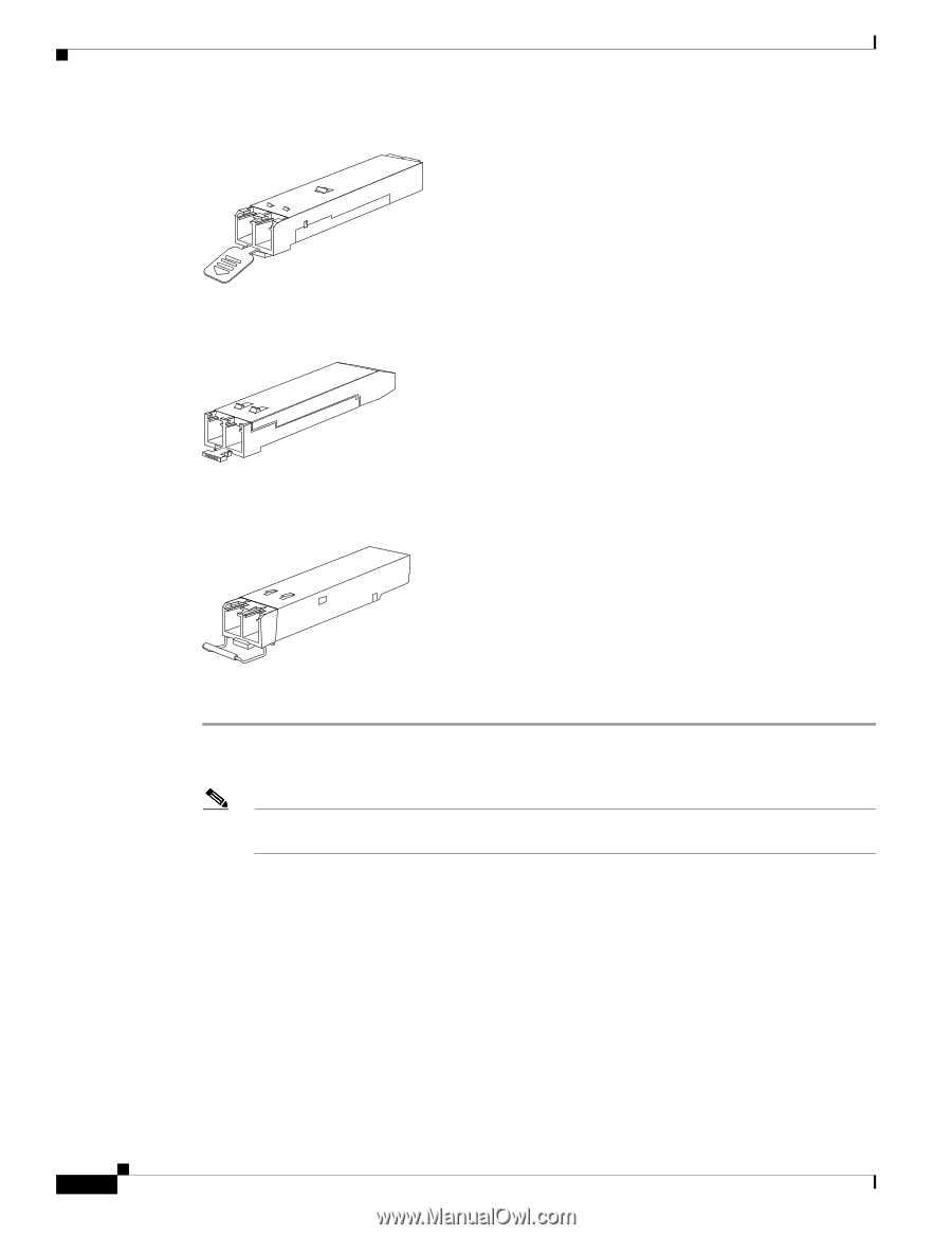
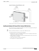
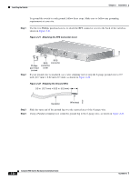
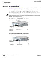
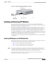
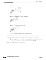
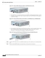
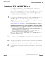
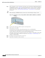
Installing and Removing SFP Modules Figure 2-28 SFP Module with a Mylar Tab Latch Chapter 2 Installation 63065 Figure 2-29 SFP Module with an Actuator Button Latch 63066 Figure 2-30 SFP Module with a Bale-Clasp Latch 63067 To insert an SFP module into the SFP module slot, follow these steps: Step 1 Attach an ESD-preventive wrist strap to your wrist and to a bare metal surface on the chassis. Step 2 Find the send (TX) and receive (RX) markings that identify the top side of the SFP module. Note On some SFP modules, the send and receive (TX and RX) markings might be replaced by arrows that show the direction of the connection, either send or receive (TX or RX). Step 3 Step 4 Align the SFP module in front of the slot opening. Insert the SFP module into the slot until you feel the connector on the module snap into place in the rear of the slot. 2-24 Catalyst 2950 Switch Hardware Installation Guide OL-6156-01
-
 1
1 -
2
-
3
-
4
-
5
-
6
-
7
-
8
-
9
-
10
-
11
-
12
-
13
-
14
-
15
-
16
-
17
-
18
-
19
-
20
-
21
-
22
-
23
-
24
-
25
-
26
-
27
-
28
-
29
-
30
-
31
-
32
-
33
-
34
-
35
-
36
-
37
-
38
-
39
-
40
-
41
-
42
-
43
-
44
-
45
-
46
-
47
-
48
-
49
-
50
-
51
-
52
-
53
-
54
-
55
-
56
-
57
-
58
-
59
-
60
-
61
-
62
-
63
-
64
-
 65
65 -
 66
66 -
 67
67 -
 68
68 -
 69
69 -
 70
70 -
 71
71 -
 72
72 -
 73
73 -
 74
74 -
 75
75 -
76
-
77
-
78
-
79
-
80
-
81
-
82
-
83
-
84
-
85
-
86
-
87
-
88
-
89
-
90
-
91
-
92
-
93
-
94
-
95
-
96
-
97
-
98
-
99
-
100
-
101
-
102
-
103
-
104
-
105
-
106
-
107
-
108
-
109
-
110
-
111
-
112
-
113
-
114
-
115
-
116
-
117
-
118
-
119
-
120
-
121
-
122
-
123
-
124
-
125
-
126
-
127
-
128
-
129
-
130
-
131
-
132
-
133
-
134
 |
 |