Cisco 2950 Hardware Installation Guide - Page 84
Connecting to SFP Modules, Connecting to Fiber-Optic SFP Modules
 |
UPC - 746320454504
View all Cisco 2950 manuals
Add to My Manuals
Save this manual to your list of manuals |
Page 84 highlights
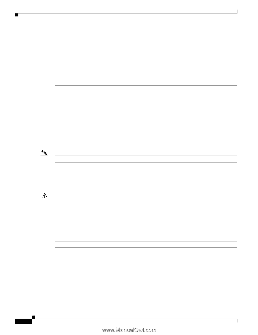
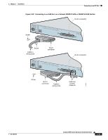
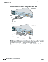
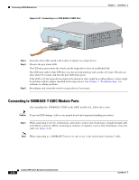
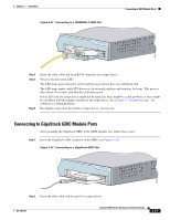
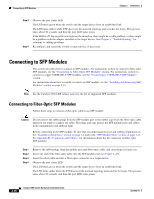
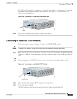
Connecting to SFP Modules Chapter 2 Installation Step 3 Step 4 Observe the port status LED. The LED turns green when the switch and the target device have an established link. The LED turns amber while STP discovers the network topology and searches for loops. This process takes about 30 seconds, and then the port LED turns green. If the LED is off, the target device might not be turned on, there might be a cable problem, or there might be a problem with the adapter installed in the target device. See Chapter 3, "Troubleshooting," for solutions to cabling problems. Reconfigure and restart the switch or target device, if necessary. Connecting to SFP Modules This section describes how to connect to SFP modules. For instructions on how to connect to fiber-optic SFP modules, see the "Connecting to Fiber-Optic SFP Modules" section. For instructions on how to connect to copper 1000BASE-T SFP modules, see the "Connecting to 1000BASE-T SFP Modules" section. For instructions about how to install or remove an SFP module, see the "Installing and Removing SFP Modules" section on page 2-23. Note See the Catalyst 2950 LRE release notes for the list of supported SFP modules. Connecting to Fiber-Optic SFP Modules Follow these steps to connect a fiber-optic cable to an SFP module: Caution Do not remove the rubber plugs from the SFP module port or the rubber caps from the fiber-optic cable until you are ready to connect the cable. The plugs and caps protect the SFP module ports and cables from contamination and ambient light. Before connecting to the SFP module, be sure that you understand the port and cabling stipulations in the "Installation Guidelines" section on page 2-4 and in the "SFP Module Slots" section on page 1-11. See Appendix B, "Connectors and Cables," for information about the LC connector on fiber-optic SFP modules. Step 1 Step 2 Step 3 Step 4 Remove the rubber plugs from the module port and fiber-optic cable, and store them for future use. Insert one end of the fiber-optic cable into the SFP module port (see Figure 2-43). Insert the other cable end into a fiber-optic connector on a target device. Observe the port status LED. The LED turns green when the switch and the target device have an established link. The LED turns amber while the STP discovers the network topology and searches for loops. This process takes about 30 seconds, and then the port LED turns green. 2-38 Catalyst 2950 Switch Hardware Installation Guide OL-6156-01
-
 1
1 -
2
-
3
-
4
-
5
-
6
-
7
-
8
-
9
-
10
-
11
-
12
-
13
-
14
-
15
-
16
-
17
-
18
-
19
-
20
-
21
-
22
-
23
-
24
-
25
-
26
-
27
-
28
-
29
-
30
-
31
-
32
-
33
-
34
-
35
-
36
-
37
-
38
-
39
-
40
-
41
-
42
-
43
-
44
-
45
-
46
-
47
-
48
-
49
-
50
-
51
-
52
-
53
-
54
-
55
-
56
-
57
-
58
-
59
-
60
-
61
-
62
-
63
-
64
-
65
-
66
-
67
-
68
-
69
-
70
-
71
-
72
-
73
-
74
-
75
-
76
-
77
-
78
-
 79
79 -
 80
80 -
 81
81 -
 82
82 -
 83
83 -
 84
84 -
 85
85 -
 86
86 -
 87
87 -
 88
88 -
 89
89 -
90
-
91
-
92
-
93
-
94
-
95
-
96
-
97
-
98
-
99
-
100
-
101
-
102
-
103
-
104
-
105
-
106
-
107
-
108
-
109
-
110
-
111
-
112
-
113
-
114
-
115
-
116
-
117
-
118
-
119
-
120
-
121
-
122
-
123
-
124
-
125
-
126
-
127
-
128
-
129
-
130
-
131
-
132
-
133
-
134
 |
 |