Cisco 2950 Hardware Installation Guide - Page 117
C-9, Completed Wiring of Terminal Block Plug, Inserting the Terminal Block in the Block Header
 |
UPC - 746320454504
View all Cisco 2950 manuals
Add to My Manuals
Save this manual to your list of manuals |
Page 117 highlights
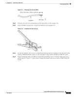
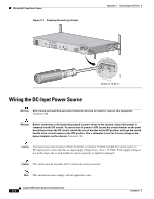
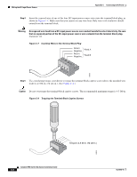
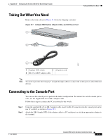
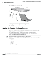
Appendix C Connecting to DC Power Wiring the DC-Input Power Source Step 6 Repeat Steps 4 and 5 for the remaining three DC-input power source wires. Figure C-9 shows the completed wiring of a terminal block plug. Figure C-9 Completed Wiring of Terminal Block Plug Return Negative Return Negative Feed A Feed B 60534 Step 7 Insert the terminal block plug in the terminal block header on the rear panel of the Catalyst 2950G-24-EI-DC switch or on the front panel of the Catalyst 2950ST-24 LRE 997 switch. Figure C-10 shows how to insert the terminal block on a Catalyst 2950G-24-EI-DC switch. Caution Secure the wires coming in from the terminal block so that they cannot be disturbed by casual contact. For example, use tie wraps to secure the wires to the rack. Figure C-10 Inserting the Terminal Block in the Block Header 36 1 - 72V 0.5A A B [email protected]. CONSOLE 65293 Tie wrap Step 8 Remove the tape from the circuit-breaker switch handle, and move the circuit-breaker handle to the on position. OL-6156-01 Catalyst 2950 Switch Hardware Installation Guide C-7
-
 1
1 -
2
-
3
-
4
-
5
-
6
-
7
-
8
-
9
-
10
-
11
-
12
-
13
-
14
-
15
-
16
-
17
-
18
-
19
-
20
-
21
-
22
-
23
-
24
-
25
-
26
-
27
-
28
-
29
-
30
-
31
-
32
-
33
-
34
-
35
-
36
-
37
-
38
-
39
-
40
-
41
-
42
-
43
-
44
-
45
-
46
-
47
-
48
-
49
-
50
-
51
-
52
-
53
-
54
-
55
-
56
-
57
-
58
-
59
-
60
-
61
-
62
-
63
-
64
-
65
-
66
-
67
-
68
-
69
-
70
-
71
-
72
-
73
-
74
-
75
-
76
-
77
-
78
-
79
-
80
-
81
-
82
-
83
-
84
-
85
-
86
-
87
-
88
-
89
-
90
-
91
-
92
-
93
-
94
-
95
-
96
-
97
-
98
-
99
-
100
-
101
-
102
-
103
-
104
-
105
-
106
-
107
-
108
-
109
-
110
-
111
-
 112
112 -
 113
113 -
 114
114 -
 115
115 -
 116
116 -
 117
117 -
 118
118 -
 119
119 -
 120
120 -
 121
121 -
 122
122 -
123
-
124
-
125
-
126
-
127
-
128
-
129
-
130
-
131
-
132
-
133
-
134
 |
 |
