Cisco 2950 Hardware Installation Guide - Page 52
Verifying Switch Operation
 |
UPC - 746320454504
View all Cisco 2950 manuals
Add to My Manuals
Save this manual to your list of manuals |
Page 52 highlights
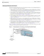
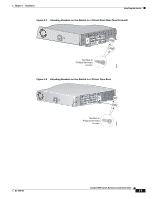
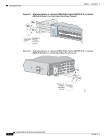
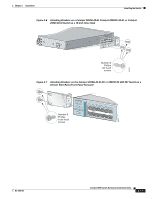
Verifying Switch Operation Chapter 2 Installation - Six number-8 Phillips flat-head screws for attaching the brackets to the switch - Four number-8 Phillips truss-head screws for attaching the brackets to the switch - Four number-12 Phillips machine screws for attaching the brackets to a rack - One cable guide and one black Phillips machine screw for attaching the cable guide to one of the mounting brackets - One RPS connector cover and two number-4 pan-head screws • DC-switch kit containing these items: - One DC terminal block plug (also called a terminal block header) - One ground lug - Two number-10-32 screws for attaching the ground lug to the switch - Two 23-inch rack-mounting brackets (with 1-inch spacing for telco racks) - Four number-8 Phillips truss-head screws for attaching the brackets to the switch - Two number-12 Phillips machine screws for attaching the brackets to a rack Note The DC-switch kit ships only with the Catalyst 2950G-24-EI-DC or Catalyst 2950ST-24 LRE 997 switch. • One RJ-45-to-DB-9 adapter cable • Product ownership registration card If you want to connect a terminal to the switch console port, you need to provide an RJ-45-to-DB-25 female DTE adapter. You can order a kit (part number ACS-DSBUASYN=) with that adapter from Cisco. Verifying Switch Operation Before installing the switch in a rack, on a wall, or on a table or shelf, you should power on the switch and verify that the switch passes POST. See Section 3, "Running Express Setup," in the getting started guide for the steps required to connect a PC to the switch console port and to power on the switch. While the switch powers on, it automatically begins POST, a series of tests that verifies that the switch functions properly. When the switch begins POST, the system LED is off. POST has completed successfully when the SYST and STAT LEDs are green. If a switch fails POST, the System LED turns amber. If POST fails, see Chapter 3, "Troubleshooting," to determine a course of action. Note POST failures are usually fatal. Call Cisco Systems if your switch does not pass POST. After a successful POST, follow these steps: Step 1 Step 2 Step 3 Turn off power to the switch. Disconnect the cables. Determine where you want to install the switch. Catalyst 2950 Switch Hardware Installation Guide 2-6 OL-6156-01
-
 1
1 -
2
-
3
-
4
-
5
-
6
-
7
-
8
-
9
-
10
-
11
-
12
-
13
-
14
-
15
-
16
-
17
-
18
-
19
-
20
-
21
-
22
-
23
-
24
-
25
-
26
-
27
-
28
-
29
-
30
-
31
-
32
-
33
-
34
-
35
-
36
-
37
-
38
-
39
-
40
-
41
-
42
-
43
-
44
-
45
-
46
-
 47
47 -
 48
48 -
 49
49 -
 50
50 -
 51
51 -
 52
52 -
 53
53 -
 54
54 -
 55
55 -
 56
56 -
 57
57 -
58
-
59
-
60
-
61
-
62
-
63
-
64
-
65
-
66
-
67
-
68
-
69
-
70
-
71
-
72
-
73
-
74
-
75
-
76
-
77
-
78
-
79
-
80
-
81
-
82
-
83
-
84
-
85
-
86
-
87
-
88
-
89
-
90
-
91
-
92
-
93
-
94
-
95
-
96
-
97
-
98
-
99
-
100
-
101
-
102
-
103
-
104
-
105
-
106
-
107
-
108
-
109
-
110
-
111
-
112
-
113
-
114
-
115
-
116
-
117
-
118
-
119
-
120
-
121
-
122
-
123
-
124
-
125
-
126
-
127
-
128
-
129
-
130
-
131
-
132
-
133
-
134
 |
 |