Cisco 2950 Hardware Installation Guide - Page 115
C-4, Terminal Block Plug, Positive and Negative Positions
 |
UPC - 746320454504
View all Cisco 2950 manuals
Add to My Manuals
Save this manual to your list of manuals |
Page 115 highlights
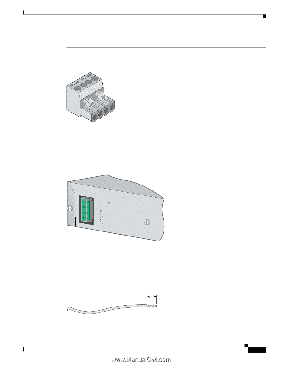
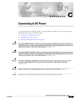
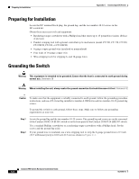
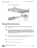
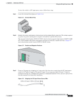
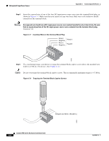
Appendix C Connecting to DC Power Wiring the DC-Input Power Source To wire the switch to a DC-input power source, follow these steps: Step 1 Locate the terminal block plug (see Figure C-4). Figure C-4 Terminal Block Plug 60530 Step 2 Identify the positive and negative feed positions for the terminal block connection. The wiring sequence is positive to positive and negative to negative for both the A and the B feed wires. The rear panel of the Catalyst 2950G-24-EI-DC switch or the front panel of the Catalyst 2950ST-24 LRE 997 switch identifies the positive and negative positions for both the A and B feed wires. Figure C-5 shows the positions on the Catalyst 2950G-24-EI-DC switch. Figure C-5 Positive and Negative Positions 36 1 - 72V 0.5A A B 65292 Step 3 Using an 18-gauge wire-stripping tool, strip each of the four wires coming from the DC-input power source to 0.27 inch (6.6 mm) ± 0.02 inch (0.5 mm). Do not strip more than 0.29 inch (7.4 mm) of insulation from the wire. Stripping more than the recommended amount of wire can leave exposed wire from the terminal block plug after installation. Figure C-6 Stripping the DC-Input Power Source Wire 0.25 in. (6.3 mm) ± 0.02 in. (0.5 mm) 60531 OL-6156-01 Catalyst 2950 Switch Hardware Installation Guide C-5
-
 1
1 -
2
-
3
-
4
-
5
-
6
-
7
-
8
-
9
-
10
-
11
-
12
-
13
-
14
-
15
-
16
-
17
-
18
-
19
-
20
-
21
-
22
-
23
-
24
-
25
-
26
-
27
-
28
-
29
-
30
-
31
-
32
-
33
-
34
-
35
-
36
-
37
-
38
-
39
-
40
-
41
-
42
-
43
-
44
-
45
-
46
-
47
-
48
-
49
-
50
-
51
-
52
-
53
-
54
-
55
-
56
-
57
-
58
-
59
-
60
-
61
-
62
-
63
-
64
-
65
-
66
-
67
-
68
-
69
-
70
-
71
-
72
-
73
-
74
-
75
-
76
-
77
-
78
-
79
-
80
-
81
-
82
-
83
-
84
-
85
-
86
-
87
-
88
-
89
-
90
-
91
-
92
-
93
-
94
-
95
-
96
-
97
-
98
-
99
-
100
-
101
-
102
-
103
-
104
-
105
-
106
-
107
-
108
-
109
-
 110
110 -
 111
111 -
 112
112 -
 113
113 -
 114
114 -
 115
115 -
 116
116 -
 117
117 -
 118
118 -
 119
119 -
 120
120 -
121
-
122
-
123
-
124
-
125
-
126
-
127
-
128
-
129
-
130
-
131
-
132
-
133
-
134
 |
 |