Cisco 2950 Hardware Installation Guide - Page 43
DC Power Connector, Cisco RPS Connector, Cisco RPS 300 - power supply
 |
UPC - 746320454504
View all Cisco 2950 manuals
Add to My Manuals
Save this manual to your list of manuals |
Page 43 highlights
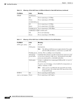
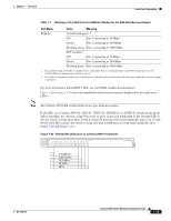
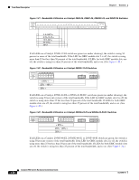
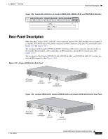
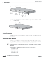
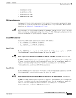
Chapter 1 Overview Rear-Panel Description • CAB-NP1200-AC-IT= • CAB-NP1200-AC-JP= • CAB-NP1200-AC-UK= • CAB-NP1200-AC-US= DC Power Connector The Catalyst 2950G-24-EI-DC and Catalyst 2950ST-24 LRE 997 switches have an internal DC-power converter. It has dual feeds (A and B) that are diode-OR-ed into a single power block. For installation instructions, see Appendix C, "Connecting to DC Power." Caution You must connect the Catalyst 2950G-24-EI-DC and 2950ST-24 LRE 997 switches only to a DC-input power source that has an input supply voltage from -36 to -72 VDC. If the supply voltage is not in this range, the switch might not operate properly or might be damaged. Cisco RPS Connector Specific Cisco RPS models support specific Catalyst 2950 switches: • Cisco RPS 300 (model PWR300-AC-RPS-N1) • Cisco RPS 675 (model PWR675-AC-RPS-N1=) Cisco RPS 300 The Cisco RPS 300 has two output levels: -48 V and 12 V with a total maximum output power of 300 W. Use the supplied RPS connector cable to connect the RPS to the switch. Warning Attach only the Cisco RPS 300 (model PWR300-AC-RPS-N1) to the RPS receptacle. Statement 100B The RPS is a 300-W redundant power system that can support six external network devices and provides DC power to one failed device at a time. It automatically senses when the internal power supply of a connected device fails and provides power to that device, preventing loss of network traffic. For more information, see the Cisco RPS 300 documentation. Cisco RPS 675 The Cisco RPS 675 has two output levels: -48 V and 12 V with a total maximum output power of 675 W. Use the supplied RPS connector cable to connect the RPS to the switch. Warning Attach only the Cisco RPS 675 (model PWR675-AC-RPS-N1=) to the RPS receptacle. Statement 100C The RPS is a 675-W redundant power system that can support six external network devices and provides DC power to one failed device at a time. It automatically senses when the internal power supply of a connected device fails and provides power to that device, preventing loss of network traffic. For more information, see the Cisco RPS 675 documentation. OL-6156-01 Catalyst 2950 Switch Hardware Installation Guide 1-23
-
 1
1 -
2
-
3
-
4
-
5
-
6
-
7
-
8
-
9
-
10
-
11
-
12
-
13
-
14
-
15
-
16
-
17
-
18
-
19
-
20
-
21
-
22
-
23
-
24
-
25
-
26
-
27
-
28
-
29
-
30
-
31
-
32
-
33
-
34
-
35
-
36
-
37
-
 38
38 -
 39
39 -
 40
40 -
 41
41 -
 42
42 -
 43
43 -
 44
44 -
 45
45 -
 46
46 -
 47
47 -
 48
48 -
49
-
50
-
51
-
52
-
53
-
54
-
55
-
56
-
57
-
58
-
59
-
60
-
61
-
62
-
63
-
64
-
65
-
66
-
67
-
68
-
69
-
70
-
71
-
72
-
73
-
74
-
75
-
76
-
77
-
78
-
79
-
80
-
81
-
82
-
83
-
84
-
85
-
86
-
87
-
88
-
89
-
90
-
91
-
92
-
93
-
94
-
95
-
96
-
97
-
98
-
99
-
100
-
101
-
102
-
103
-
104
-
105
-
106
-
107
-
108
-
109
-
110
-
111
-
112
-
113
-
114
-
115
-
116
-
117
-
118
-
119
-
120
-
121
-
122
-
123
-
124
-
125
-
126
-
127
-
128
-
129
-
130
-
131
-
132
-
133
-
134
 |
 |
