Cisco 2950 Hardware Installation Guide - Page 67
Crimping the Ground Lug, Torquing Ground-Lug Screws, Step 5
 |
UPC - 746320454504
View all Cisco 2950 manuals
Add to My Manuals
Save this manual to your list of manuals |
Page 67 highlights
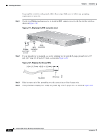
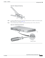
Chapter 2 Installation Figure 2-23 Crimping the Ground Lug Installing the Switch 60529 111399 Step 5 Step 6 Use the two number-10-32 screws to attach the ground lug and wire assembly to the switch rear panel RPS connector cover, as shown in Figure 2-24. Using a ratcheting torque screwdriver, torque each ground-lug screw to 15 lbf-in. (240 ozf-in.) Figure 2-24 Torquing Ground-Lug Screws 12005R@[email protected]~~ [email protected]. CONSOLE Torque to 15 lbf-in. OL-6156-01 Catalyst 2950 Switch Hardware Installation Guide 2-21
-
 1
1 -
2
-
3
-
4
-
5
-
6
-
7
-
8
-
9
-
10
-
11
-
12
-
13
-
14
-
15
-
16
-
17
-
18
-
19
-
20
-
21
-
22
-
23
-
24
-
25
-
26
-
27
-
28
-
29
-
30
-
31
-
32
-
33
-
34
-
35
-
36
-
37
-
38
-
39
-
40
-
41
-
42
-
43
-
44
-
45
-
46
-
47
-
48
-
49
-
50
-
51
-
52
-
53
-
54
-
55
-
56
-
57
-
58
-
59
-
60
-
61
-
 62
62 -
 63
63 -
 64
64 -
 65
65 -
 66
66 -
 67
67 -
 68
68 -
 69
69 -
 70
70 -
 71
71 -
 72
72 -
73
-
74
-
75
-
76
-
77
-
78
-
79
-
80
-
81
-
82
-
83
-
84
-
85
-
86
-
87
-
88
-
89
-
90
-
91
-
92
-
93
-
94
-
95
-
96
-
97
-
98
-
99
-
100
-
101
-
102
-
103
-
104
-
105
-
106
-
107
-
108
-
109
-
110
-
111
-
112
-
113
-
114
-
115
-
116
-
117
-
118
-
119
-
120
-
121
-
122
-
123
-
124
-
125
-
126
-
127
-
128
-
129
-
130
-
131
-
132
-
133
-
134
 |
 |
2-21
Catalyst 2950 Switch Hardware Installation Guide
OL-6156-01
Chapter 2
Installation
Installing the Switch
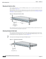
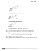
Figure 2-23
Crimping the Ground Lug
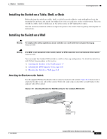
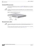
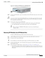
Step 5
Use the two number-10-32 screws to attach the ground lug and wire assembly to the switch rear panel
RPS connector cover, as shown in
Figure 2-24
.
Step 6
Using a ratcheting torque screwdriver, torque each ground-lug screw to 15 lbf-in. (240 ozf-in.)
Figure 2-24
Torquing Ground-Lug Screws
60529
111399
Torque to 15 lbf-in.
RATING
100-127V~
@ 1A
200-240V~
@0.5A
50-60Hz
DC INPUT FOR REMOTE
POWER SUPPLY
SPECIFIED IN MANUAL.
+12V
@4.5A
CONSOLE