Cisco 2950 Hardware Installation Guide - Page 69
Installing and Removing SFP Modules, Installing SFP Modules into SFP Module Slots - end life
 |
UPC - 746320454504
View all Cisco 2950 manuals
Add to My Manuals
Save this manual to your list of manuals |
Page 69 highlights
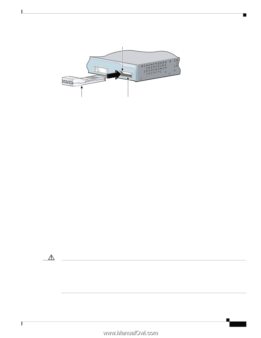
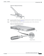
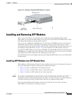
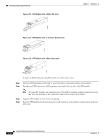
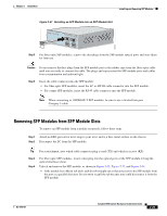
Chapter 2 Installation Installing and Removing SFP Modules Figure 2-27 Installing a GigaStack GBIC Module in a Switch Metal flap door 1 Catalyst 2950 SERIES 2 74533 GigaStack GBIC module GBIC module slot Installing and Removing SFP Modules These sections describe how to install and remove small-form-factor pluggable (SFP) modules. SFP modules are inserted into SFP module slots on the front of the Catalyst 2950 LRE switches. These field-replaceable modules provide the uplink interfaces. You can use any combination of SFP modules. See the Catalyst 2950 LRE release notes for the list of SFP modules that the Catalyst 2950 LRE switch supports. Each port must match the wave-length specifications on the other end of the cable, and for reliable communications, the cable must not exceed the stipulated cable length. Refer to Table 1-2 for cable stipulations for SFP module connections. Use only Cisco SFP modules on the Catalyst 2950 LRE switch. Each SFP module has an internal serial EEPROM that is encoded with security information. This encoding provides a way for Cisco to identify and validate that the SFP module meets the requirements for the switch. For detailed instructions on installing, removing, and cabling the SFP module, refer to your SFP module documentation. Installing SFP Modules into SFP Module Slots SFP modules use different types of latches for their installation and extraction. Determine which type of latch your SFP module uses before following the installation procedure: • Figure 2-28 shows an SFP module with a Mylar tab latch. • Figure 2-29 shows an SFP module with an actuator button latch. • Figure 2-30 shows an SFP module that has a bale-clasp latch. Caution We strongly recommend that you do not install or remove the SFP module with fiber-optic cables attached to it because of the potential damage to the cables, the cable connector, or the optical interfaces in the SFP module. Disconnect all cables before removing or installing an SFP module. Removing and installing an SFP module can shorten its useful life. Do not remove and insert SFP modules more often than is absolutely necessary. OL-6156-01 Catalyst 2950 Switch Hardware Installation Guide 2-23
-
 1
1 -
2
-
3
-
4
-
5
-
6
-
7
-
8
-
9
-
10
-
11
-
12
-
13
-
14
-
15
-
16
-
17
-
18
-
19
-
20
-
21
-
22
-
23
-
24
-
25
-
26
-
27
-
28
-
29
-
30
-
31
-
32
-
33
-
34
-
35
-
36
-
37
-
38
-
39
-
40
-
41
-
42
-
43
-
44
-
45
-
46
-
47
-
48
-
49
-
50
-
51
-
52
-
53
-
54
-
55
-
56
-
57
-
58
-
59
-
60
-
61
-
62
-
63
-
 64
64 -
 65
65 -
 66
66 -
 67
67 -
 68
68 -
 69
69 -
 70
70 -
 71
71 -
 72
72 -
 73
73 -
 74
74 -
75
-
76
-
77
-
78
-
79
-
80
-
81
-
82
-
83
-
84
-
85
-
86
-
87
-
88
-
89
-
90
-
91
-
92
-
93
-
94
-
95
-
96
-
97
-
98
-
99
-
100
-
101
-
102
-
103
-
104
-
105
-
106
-
107
-
108
-
109
-
110
-
111
-
112
-
113
-
114
-
115
-
116
-
117
-
118
-
119
-
120
-
121
-
122
-
123
-
124
-
125
-
126
-
127
-
128
-
129
-
130
-
131
-
132
-
133
-
134
 |
 |