Cisco 2950 Hardware Installation Guide - Page 114
Wiring the DC-Input Power Source
 |
UPC - 746320454504
View all Cisco 2950 manuals
Add to My Manuals
Save this manual to your list of manuals |
Page 114 highlights
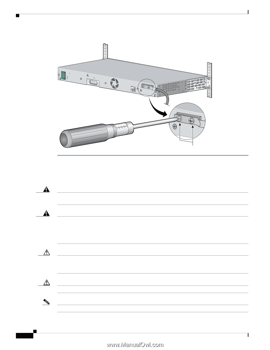
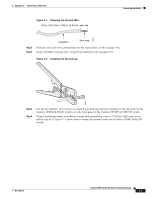
Wiring the DC-Input Power Source Figure C-3 Torquing Ground-Lug Screws 36 - 72V 1 - 0.5A A B [email protected]. CONSOLE Appendix C Connecting to DC Power 65295 Torque to 15 lbf-in. Wiring the DC-Input Power Source Warning Only trained and qualified personnel should be allowed to install or replace this equipment. Statement 1030 Warning Before connecting or disconnecting ground or power wires to the chassis, ensure that power is removed from the DC circuit. To ensure that all power is OFF, locate the circuit breaker on the panel board that services the DC circuit, switch the circuit breaker to the OFF position, and tape the switch handle of the circuit breaker in the OFF position. Use a voltmeter to test for 0 (zero) voltage at the power terminals on the chassis. Statement 196 Caution You must connect the Catalyst 2950G-24-EI-DC or Catalyst 2950ST-24 LRE 997 switch only to a DC-input power source that has an input supply voltage from -36 to -72 VDC. If the supply voltage is not in this range, the switch might not operate properly or might be damaged. Caution The switch must be installed with 5-A-branch-circuit protection. Note This installation must comply with all applicable codes. Catalyst 2950 Switch Hardware Installation Guide C-4 OL-6156-01
-
 1
1 -
2
-
3
-
4
-
5
-
6
-
7
-
8
-
9
-
10
-
11
-
12
-
13
-
14
-
15
-
16
-
17
-
18
-
19
-
20
-
21
-
22
-
23
-
24
-
25
-
26
-
27
-
28
-
29
-
30
-
31
-
32
-
33
-
34
-
35
-
36
-
37
-
38
-
39
-
40
-
41
-
42
-
43
-
44
-
45
-
46
-
47
-
48
-
49
-
50
-
51
-
52
-
53
-
54
-
55
-
56
-
57
-
58
-
59
-
60
-
61
-
62
-
63
-
64
-
65
-
66
-
67
-
68
-
69
-
70
-
71
-
72
-
73
-
74
-
75
-
76
-
77
-
78
-
79
-
80
-
81
-
82
-
83
-
84
-
85
-
86
-
87
-
88
-
89
-
90
-
91
-
92
-
93
-
94
-
95
-
96
-
97
-
98
-
99
-
100
-
101
-
102
-
103
-
104
-
105
-
106
-
107
-
108
-
 109
109 -
 110
110 -
 111
111 -
 112
112 -
 113
113 -
 114
114 -
 115
115 -
 116
116 -
 117
117 -
 118
118 -
 119
119 -
120
-
121
-
122
-
123
-
124
-
125
-
126
-
127
-
128
-
129
-
130
-
131
-
132
-
133
-
134
 |
 |