Cisco 2950 Hardware Installation Guide - Page 75
Connecting to 100BASE-FX and 1000BASE-SX Ports - status lights
 |
UPC - 746320454504
View all Cisco 2950 manuals
Add to My Manuals
Save this manual to your list of manuals |
Page 75 highlights
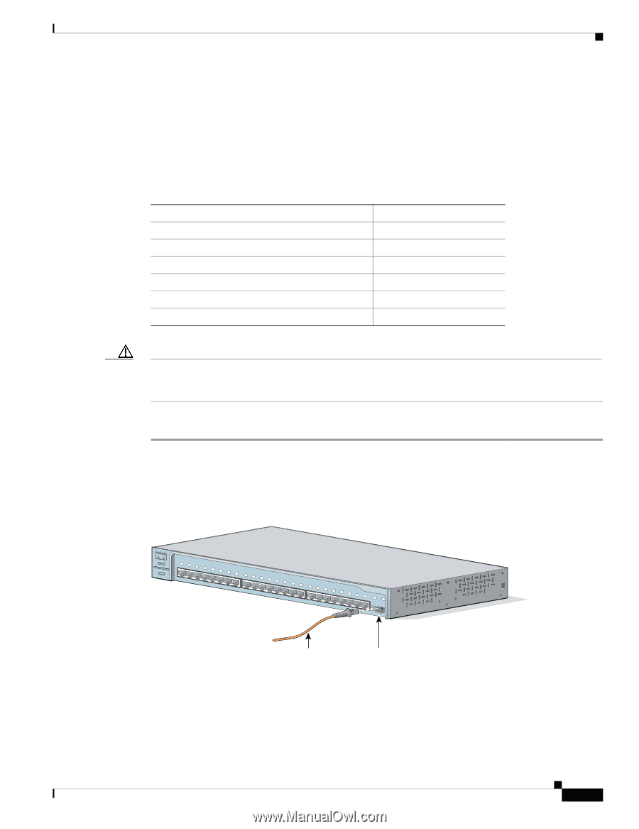
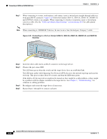
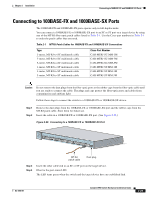
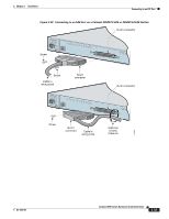
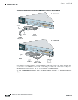
Chapter 2 Installation Connecting to 100BASE-FX and 1000BASE-SX Ports Connecting to 100BASE-FX and 1000BASE-SX Ports The 100BASE-FX and 1000BASE-SX ports operate only in full-duplex mode. You can connect a 100BASE-FX or 1000BASE-SX port to an SC or ST port on a target device by using one of the MT-RJ fiber-optic patch cables listed in Table 2-1. Use the Cisco part numbers in Table 2-1 to order the patch cables that you need. Table 2-1 MT-RJ Patch Cables for 100BASE-FX and 1000BASE-SX Connections Type 1-meter, MT-RJ-to-SC multimode cable 3-meter, MT-RJ-to-SC multimode cable 5-meter, MT-RJ-to-SC multimode cable 1-meter, MT-RJ-to-ST multimode cable 3-meter, MT-RJ-to-ST multimode cable 5-meter, MT-RJ-to-ST multimode cable Cisco Part Number CAB-MTRJ-SC-MM-1M CAB-MTRJ-SC-MM-3M CAB-MTRJ-SC-MM-5M CAB-MTRJ-ST-MM-1M CAB-MTRJ-ST-MM-3M CAB-MTRJ-ST-MM-5M Caution Do not remove the dust plugs from the fiber-optic ports or the rubber caps from the fiber-optic cable until you are ready to connect the cable. The plugs and caps protect the fiber-optic ports and cables from contamination and ambient light. Follow these steps to connect the switch to a 100BASE-FX or 1000BASE-SX device: Step 1 Step 2 Remove the dust plugs from the 100BASE-FX or 1000BASE-SX port and the rubber caps from the MT-RJ patch cable. Store them for future use. Insert the cable in a 100BASE-FX or 1000BASE-SX port. (See Figure 2-36.) Figure 2-36 Connecting to a 100BASE-FX or 1000BASE-SX Port 45571 SYST RPS STAT UTIL DUPLX SPEED MODE 1x 2x 3x 4x 5x 6x 7x 8x 9x 10x 11x 10Base-T / 100Base-TX 12x 13x 14x 15x 16x 17x 18x 19x 20x 21x 22x 23x Catalyst 2950 SERIES 24x 100Base-FX 25 26 MT-RJ patch cable Dust plug Step 3 Step 4 Insert the other cable end in an SC or ST port on the target device. Observe the port status LED. The LED turns green when the switch and the target device have an established link. OL-6156-01 Catalyst 2950 Switch Hardware Installation Guide 2-29
-
 1
1 -
2
-
3
-
4
-
5
-
6
-
7
-
8
-
9
-
10
-
11
-
12
-
13
-
14
-
15
-
16
-
17
-
18
-
19
-
20
-
21
-
22
-
23
-
24
-
25
-
26
-
27
-
28
-
29
-
30
-
31
-
32
-
33
-
34
-
35
-
36
-
37
-
38
-
39
-
40
-
41
-
42
-
43
-
44
-
45
-
46
-
47
-
48
-
49
-
50
-
51
-
52
-
53
-
54
-
55
-
56
-
57
-
58
-
59
-
60
-
61
-
62
-
63
-
64
-
65
-
66
-
67
-
68
-
69
-
 70
70 -
 71
71 -
 72
72 -
 73
73 -
 74
74 -
 75
75 -
 76
76 -
 77
77 -
 78
78 -
 79
79 -
 80
80 -
81
-
82
-
83
-
84
-
85
-
86
-
87
-
88
-
89
-
90
-
91
-
92
-
93
-
94
-
95
-
96
-
97
-
98
-
99
-
100
-
101
-
102
-
103
-
104
-
105
-
106
-
107
-
108
-
109
-
110
-
111
-
112
-
113
-
114
-
115
-
116
-
117
-
118
-
119
-
120
-
121
-
122
-
123
-
124
-
125
-
126
-
127
-
128
-
129
-
130
-
131
-
132
-
133
-
134
 |
 |