Cisco 2950 Hardware Installation Guide - Page 32
SFP Module, Wavelength, nanometers, Fiber Type, Core Size, micron, Modal, Bandwidth, MHz/km
 |
UPC - 746320454504
View all Cisco 2950 manuals
Add to My Manuals
Save this manual to your list of manuals |
Page 32 highlights
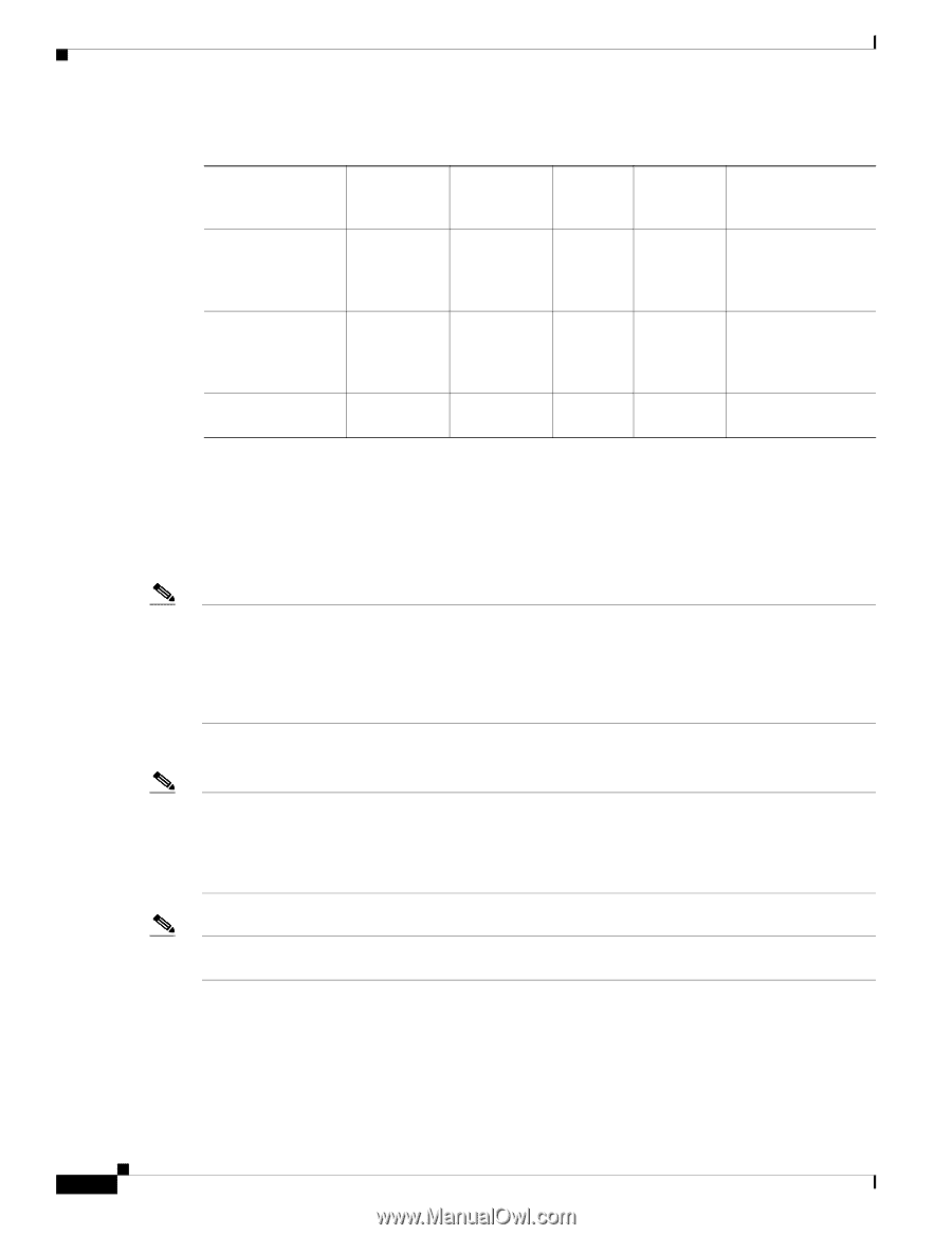
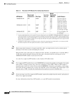
Front-Panel Description Chapter 1 Overview Table 1-2 Fiber-Optic SFP Module Port Cabling Specifications SFP Module Wavelength (nanometers) Fiber Type Core Size (micron) Modal Bandwidth (MHz/km) Cable Distance 1000BASE-SX 850 1000BASE-LX/LH 1300 MMF MMF1 SMF 62.5 160 62.5 200 50 400 50 500 62.5 500 50 400 50 500 9/10 - 722 feet (220 m) 902 feet (275 m) 1640 feet (500 m) 1804 feet (550 m) 1804 feet (550 m) 1804 feet (550 m) 1804 feet (550 m) 32,810 feet (10 km) 1000BASE-ZX 1550 SMF 9/10 - 43.4 to 62 miles (70 to 100 km)2 1. A mode-conditioning patch cord is required. Using an ordinary patch cord with MMF, 1000BASE-LX/LH SFP modules, and a short link distance can cause transceiver saturation, resulting in an elevated bit error rate (BER). When using the LX/LH SFP module with 62.5-micron diameter MMF, you must also install a mode-conditioning patch cord between the SFP module and the MMF cable on both the sending and receiving ends of the link. The mode-conditioning patch cord is required for link distances greater than 984 feet (300 m). 2. 1000BASE-ZX SFP modules can send up to 62 miles (100 km) by using dispersion-shifted SMF or low-attenuation SMF; the distance depends on the fiber quality, the number of splices, and the connectors. Note When using shorter distances of single-mode fiber cable, you might need to insert an inline optical attenuator in the link to avoid overloading the receiver. When the fiber-optic cable span is less than15.43 miles (25 km), you should insert a 5-decibel (dB) or 10-dB inline optical attenuator between the fiber-optic cable plant and the receiving port on the 1000BASE-ZX SFP module at each end of the link. Use only Cisco-approved SFP modules on the Catalyst 2950 LRE switch. Note Cisco-approved SFP modules have a serial EEPROM that contains the module serial number, the vendor name and ID, a unique security code, and cyclic redundancy check (CRC). When an SFP module is inserted in the switch, the switch software reads the EEPROM to check the serial number, vendor name, and vendor ID and recomputes the security code and CRC. If the serial number, the vendor name or ID, security code, or CRC is invalid, the switch places the interface in an error-disabled state. Note If you are using a non-Cisco approved SFP module, remove the module from the switch, and replace it with a Cisco-approved module. For more information about these SFP modules, see your SFP module documentation. 1-12 Catalyst 2950 Switch Hardware Installation Guide OL-6156-01
-
 1
1 -
2
-
3
-
4
-
5
-
6
-
7
-
8
-
9
-
10
-
11
-
12
-
13
-
14
-
15
-
16
-
17
-
18
-
19
-
20
-
21
-
22
-
23
-
24
-
25
-
26
-
 27
27 -
 28
28 -
 29
29 -
 30
30 -
 31
31 -
 32
32 -
 33
33 -
 34
34 -
 35
35 -
 36
36 -
 37
37 -
38
-
39
-
40
-
41
-
42
-
43
-
44
-
45
-
46
-
47
-
48
-
49
-
50
-
51
-
52
-
53
-
54
-
55
-
56
-
57
-
58
-
59
-
60
-
61
-
62
-
63
-
64
-
65
-
66
-
67
-
68
-
69
-
70
-
71
-
72
-
73
-
74
-
75
-
76
-
77
-
78
-
79
-
80
-
81
-
82
-
83
-
84
-
85
-
86
-
87
-
88
-
89
-
90
-
91
-
92
-
93
-
94
-
95
-
96
-
97
-
98
-
99
-
100
-
101
-
102
-
103
-
104
-
105
-
106
-
107
-
108
-
109
-
110
-
111
-
112
-
113
-
114
-
115
-
116
-
117
-
118
-
119
-
120
-
121
-
122
-
123
-
124
-
125
-
126
-
127
-
128
-
129
-
130
-
131
-
132
-
133
-
134
 |
 |