Cisco 2950 Hardware Installation Guide - Page 112
Preparing for Installation, Grounding the Switch
 |
UPC - 746320454504
View all Cisco 2950 manuals
Add to My Manuals
Save this manual to your list of manuals |
Page 112 highlights
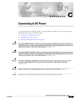
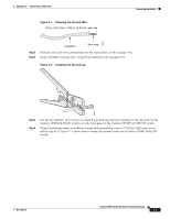
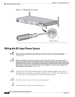
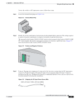
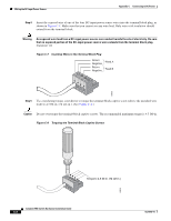
Preparing for Installation Appendix C Connecting to DC Power Preparing for Installation Locate the DC terminal block plug, the ground lug, and the two number-10-32 screws in the DC-switch kit. Obtain these necessary tools and equipment: • Ratcheting torque screwdriver with a Phillips head that exerts up to 15 pound-force inches (lbf-in.) of pressure • Panduit crimping tool with optional controlled cycle mechanism (model CT-700, CT-720, CT-920, CT-920CH, CT-930, or CT-940CH) • 6-gauge copper ground wire (insulated or noninsulated) • Four leads of 18-gauge copper wire • Wire-stripping tools for stripping 6- and 18-gauge wires Grounding the Switch Warning This equipment is intended to be grounded. Ensure that the host is connected to earth ground during normal use. Statement 39 Warning When installing the unit, always make the ground connection first and disconnect it last. Statement 42 Caution To make sure that the equipment is reliably connected to earth ground, follow the grounding procedure instructions, and use a UL-listed lug suitable for number-6 AWG wire and two number-10-32 ground-lug screws. To ground the switch to earth ground, follow these steps. Make sure to follow any grounding requirements at your site. Step 1 Step 2 Locate the ground lug and the two number-10-32 screws. The ground lug and screws are on the rear panel of the Catalyst 2950G-24-EI-DC switch or on the front panel of the Catalyst 2950ST-24 LRE 997 switch. Use a standard Phillips screwdriver or a ratcheting torque screwdriver with a Phillips head. Set the screws and the ground lug aside. If your ground wire is insulated, use a wire stripping tool to strip the 6-gauge ground wire to 0.5 inch (12.7 millimeter [mm]) ± 0.02 inch (0.5 mm) as shown in Figure C-1. Catalyst 2950 Switch Hardware Installation Guide C-2 OL-6156-01
-
 1
1 -
2
-
3
-
4
-
5
-
6
-
7
-
8
-
9
-
10
-
11
-
12
-
13
-
14
-
15
-
16
-
17
-
18
-
19
-
20
-
21
-
22
-
23
-
24
-
25
-
26
-
27
-
28
-
29
-
30
-
31
-
32
-
33
-
34
-
35
-
36
-
37
-
38
-
39
-
40
-
41
-
42
-
43
-
44
-
45
-
46
-
47
-
48
-
49
-
50
-
51
-
52
-
53
-
54
-
55
-
56
-
57
-
58
-
59
-
60
-
61
-
62
-
63
-
64
-
65
-
66
-
67
-
68
-
69
-
70
-
71
-
72
-
73
-
74
-
75
-
76
-
77
-
78
-
79
-
80
-
81
-
82
-
83
-
84
-
85
-
86
-
87
-
88
-
89
-
90
-
91
-
92
-
93
-
94
-
95
-
96
-
97
-
98
-
99
-
100
-
101
-
102
-
103
-
104
-
105
-
106
-
 107
107 -
 108
108 -
 109
109 -
 110
110 -
 111
111 -
 112
112 -
 113
113 -
 114
114 -
 115
115 -
 116
116 -
 117
117 -
118
-
119
-
120
-
121
-
122
-
123
-
124
-
125
-
126
-
127
-
128
-
129
-
130
-
131
-
132
-
133
-
134
 |
 |
