Cisco 2950 Hardware Installation Guide - Page 53
Installing the Switch, Installing the Switch in a Rack - 2950t 24
 |
UPC - 746320454504
View all Cisco 2950 manuals
Add to My Manuals
Save this manual to your list of manuals |
Page 53 highlights
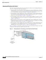
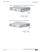
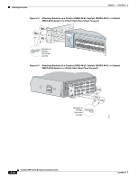
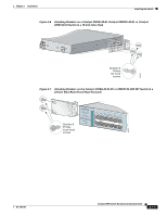
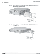
Chapter 2 Installation Installing the Switch Installing the Switch This section describes these installation procedures: • Installing the Switch in a Rack, page 2-7 • Installing the Switch on a Table, Shelf, or Desk, page 2-17 • Installing the Switch on a Wall, page 2-17 • Installing the Optional AC Ground Kit for Catalyst 2950 Switches, page 2-19 Installing the Switch in a Rack Use these instructions to install the switch in a rack: Warning To prevent bodily injury when mounting or servicing this unit in a rack, you must take special precautions to ensure that the system remains stable. The following guidelines are provided to ensure your safety: • This unit should be mounted at the bottom of the rack if it is the only unit in the rack. • When mounting this unit in a partially filled rack, load the rack from the bottom to the top with the heaviest component at the bottom of the rack. • If the rack is provided with stabilizing devices, install the stabilizers before mounting or servicing the unit in the rack. Statement 1006 Note Figure 2-1 to Figure 2-15 show the Catalyst 2950-24, 2950G-24-EI-DC, and 2950G-48-EI switches as examples. You can install other Catalyst 2950 switches in a rack as shown in these illustrations. To install the switch in a 19-, 23-, or 24-inch rack, follow these steps: 1. Attaching the Brackets to the Switch, page 2-8 2. Mounting the Switch in a Rack, page 2-16 3. Attaching the Optional Cable Guide, page 2-16 Note Installing a Catalyst 2950G-48-EI, Catalyst 2950SX-48-SI, or Catalyst 2950T-48-SI switch in a 23-inch or 24-inch rack requires an optional bracket kit not included with the switch. You can order a kit containing the 23-inch or 24-inch rack-mounting brackets and hardware from Cisco (part number RCKMNT-1RU=). OL-6156-01 Catalyst 2950 Switch Hardware Installation Guide 2-7
-
 1
1 -
2
-
3
-
4
-
5
-
6
-
7
-
8
-
9
-
10
-
11
-
12
-
13
-
14
-
15
-
16
-
17
-
18
-
19
-
20
-
21
-
22
-
23
-
24
-
25
-
26
-
27
-
28
-
29
-
30
-
31
-
32
-
33
-
34
-
35
-
36
-
37
-
38
-
39
-
40
-
41
-
42
-
43
-
44
-
45
-
46
-
47
-
 48
48 -
 49
49 -
 50
50 -
 51
51 -
 52
52 -
 53
53 -
 54
54 -
 55
55 -
 56
56 -
 57
57 -
 58
58 -
59
-
60
-
61
-
62
-
63
-
64
-
65
-
66
-
67
-
68
-
69
-
70
-
71
-
72
-
73
-
74
-
75
-
76
-
77
-
78
-
79
-
80
-
81
-
82
-
83
-
84
-
85
-
86
-
87
-
88
-
89
-
90
-
91
-
92
-
93
-
94
-
95
-
96
-
97
-
98
-
99
-
100
-
101
-
102
-
103
-
104
-
105
-
106
-
107
-
108
-
109
-
110
-
111
-
112
-
113
-
114
-
115
-
116
-
117
-
118
-
119
-
120
-
121
-
122
-
123
-
124
-
125
-
126
-
127
-
128
-
129
-
130
-
131
-
132
-
133
-
134
 |
 |