Cisco 2950 Hardware Installation Guide - Page 74
Connecting to a Port on Catalyst 2950-12 - 2950c
 |
UPC - 746320454504
View all Cisco 2950 manuals
Add to My Manuals
Save this manual to your list of manuals |
Page 74 highlights
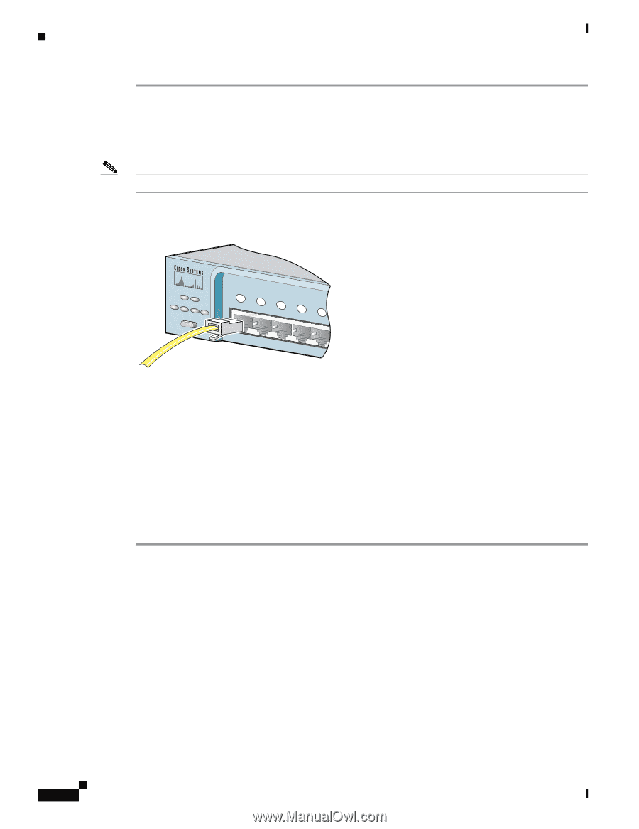
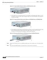
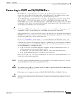
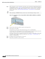
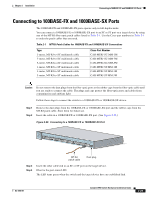
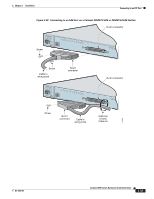
Connecting to 10/100 and 10/100/1000 Ports Chapter 2 Installation Step 1 When connecting to servers, workstations, and routers, insert a twisted-pair straight-through cable in a front-panel RJ-45 connector. Figure 2-35 shows the Catalyst 2950-12, 2950-24, 2950C-24, 2950SX-24, and 2950T-24 switch as an example. When connecting to switches or repeaters, insert a twisted-pair crossover cable. (See the "Cable and Adapter Specifications" section on page B-6 for cable-pinout descriptions.) Note When connecting to 1000BASE-T devices, be sure to use a four twisted-pair, Category 5 cable. Figure 2-35 Connecting to a Port on Catalyst 2950-12, 2950-24, 2950C-24, 2950SX-24, and 2950T-24 Switches SYST RPS STAT UTIL DUPLX SPEED MODE 1x 2x 3x 4x 5x 45576 Step 2 Step 3 Step 4 Step 5 Insert the other cable end in an RJ-45 connector on the target device. Observe the port status LED. The LED turns green when the switch and the target device have an established link. The LED turns amber while Spanning Tree Protocol (STP) discovers the network topology and searches for loops. This process takes about 30 seconds, and then the LED turns green. If the LED is off, the target device might not be turned on, there might be a cable problem, or there might be a problem with the adapter installed in the target device. See Chapter 3, "Troubleshooting," for solutions to cabling problems. Reconfigure and restart the target device if necessary. Repeat Steps 1 through 4 to connect each port. 2-28 Catalyst 2950 Switch Hardware Installation Guide OL-6156-01
-
 1
1 -
2
-
3
-
4
-
5
-
6
-
7
-
8
-
9
-
10
-
11
-
12
-
13
-
14
-
15
-
16
-
17
-
18
-
19
-
20
-
21
-
22
-
23
-
24
-
25
-
26
-
27
-
28
-
29
-
30
-
31
-
32
-
33
-
34
-
35
-
36
-
37
-
38
-
39
-
40
-
41
-
42
-
43
-
44
-
45
-
46
-
47
-
48
-
49
-
50
-
51
-
52
-
53
-
54
-
55
-
56
-
57
-
58
-
59
-
60
-
61
-
62
-
63
-
64
-
65
-
66
-
67
-
68
-
 69
69 -
 70
70 -
 71
71 -
 72
72 -
 73
73 -
 74
74 -
 75
75 -
 76
76 -
 77
77 -
 78
78 -
 79
79 -
80
-
81
-
82
-
83
-
84
-
85
-
86
-
87
-
88
-
89
-
90
-
91
-
92
-
93
-
94
-
95
-
96
-
97
-
98
-
99
-
100
-
101
-
102
-
103
-
104
-
105
-
106
-
107
-
108
-
109
-
110
-
111
-
112
-
113
-
114
-
115
-
116
-
117
-
118
-
119
-
120
-
121
-
122
-
123
-
124
-
125
-
126
-
127
-
128
-
129
-
130
-
131
-
132
-
133
-
134
 |
 |