Cisco 2950 Hardware Installation Guide - Page 30
GBIC Module Ports
 |
UPC - 746320454504
View all Cisco 2950 manuals
Add to My Manuals
Save this manual to your list of manuals |
Page 30 highlights
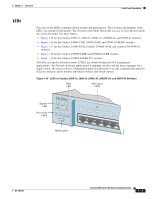
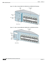
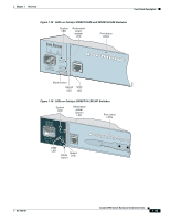
Front-Panel Description Chapter 1 Overview For limitations and restrictions when you use a POTS splitter with the Catalyst 2950 LRE switches and Cisco LRE CPE, see the "Limitations and Restrictions with POTS Splitters" section on page 2-31. If the installation does not have a PBX, a certified, homologated POTS splitter is required to connect directly to the PSTN. For more information about homologated POTS splitters, contact your Cisco sales representative. If a connection to a telephone network is not required, a splitter is not needed, and the switch can connect directly to the patch panel. For more information about the Cisco LRE CPE devices, see the Cisco LRE CPE Hardware Installation Guide. GBIC Module Ports The GBIC module slots support these modules: • 1000BASE-SX GBIC module for fiber-optic connections that cannot exceed 1804 feet (550 meters). • 1000BASE-LX/LH GBIC module for fiber-optic connections that cannot exceed 32,810 feet (10 kilometers). • 1000BASE-ZX GBIC module for fiber-optic connections that cannot exceed 328,100 feet (100 kilometers). • 1000BASE-T GBIC module for copper connections that cannot exceed 328 feet (100 meters). • CWDM GBIC module for single-mode fiber-optic connections that cannot exceed 393,719 feet (120 kilometers). • GigaStack GBIC module for creating a 1-Gbps stack configuration of up to nine supported switches. The GigaStack GBIC supports one full-duplex link (in a point-to-point configuration) or up to nine half-duplex links (in a stack configuration) to other Gigabit Ethernet devices. Using the required Cisco proprietary signaling and cabling, the GigaStack GBIC-to-GigaStack GBIC connection cannot exceed 3 feet (1 meter). Note Cisco-approved CWDM GBIC modules have a serial EEPROM that contains the module serial number, the vendor name and ID, a unique security code, and cyclic redundancy check (CRC). When a GBIC module is inserted in the switch, the switch software reads the EEPROM to check the serial number, vendor name, and vendor ID and recomputes the security code and CRC. If the serial number, the vendor name or ID, security code, or CRC is invalid, the switch places the interface in an error-disabled state. Note If you are using a non-Cisco approved CWDM GBIC module, remove the module from the switch, and replace it with a Cisco-approved module. For more information about these GBIC modules, see your GBIC module documentation. 1-10 Catalyst 2950 Switch Hardware Installation Guide OL-6156-01
-
 1
1 -
2
-
3
-
4
-
5
-
6
-
7
-
8
-
9
-
10
-
11
-
12
-
13
-
14
-
15
-
16
-
17
-
18
-
19
-
20
-
21
-
22
-
23
-
24
-
 25
25 -
 26
26 -
 27
27 -
 28
28 -
 29
29 -
 30
30 -
 31
31 -
 32
32 -
 33
33 -
 34
34 -
 35
35 -
36
-
37
-
38
-
39
-
40
-
41
-
42
-
43
-
44
-
45
-
46
-
47
-
48
-
49
-
50
-
51
-
52
-
53
-
54
-
55
-
56
-
57
-
58
-
59
-
60
-
61
-
62
-
63
-
64
-
65
-
66
-
67
-
68
-
69
-
70
-
71
-
72
-
73
-
74
-
75
-
76
-
77
-
78
-
79
-
80
-
81
-
82
-
83
-
84
-
85
-
86
-
87
-
88
-
89
-
90
-
91
-
92
-
93
-
94
-
95
-
96
-
97
-
98
-
99
-
100
-
101
-
102
-
103
-
104
-
105
-
106
-
107
-
108
-
109
-
110
-
111
-
112
-
113
-
114
-
115
-
116
-
117
-
118
-
119
-
120
-
121
-
122
-
123
-
124
-
125
-
126
-
127
-
128
-
129
-
130
-
131
-
132
-
133
-
134
 |
 |
