Cisco 2950 Hardware Installation Guide - Page 51
Verifying Package Contents, Catalyst 2950 Switch Getting Started Guide
 |
UPC - 746320454504
View all Cisco 2950 manuals
Add to My Manuals
Save this manual to your list of manuals |
Page 51 highlights
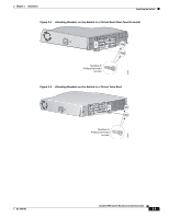
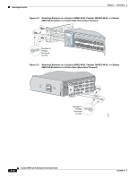
Chapter 2 Installation Preparing for Installation • For GigaStack GBIC module ports, the cable length from a switch to an attached device cannot exceed 3 feet (1 meter). • For Long-Reach Ethernet (LRE) ports, cable-length specifications vary. See the "LRE Port" section on page 1-9. • Operating environment is within the ranges listed in Appendix A, "Technical Specifications." • Clearance to front and rear panels meet these conditions: - Front-panel LEDs can be easily read. - Access to ports is sufficient for unrestricted cabling. - Rear-panel AC power connector on switches other than the LRE switches is within reach of an AC power outlet. - Rear-panel direct current (DC) power connector on the Catalyst 2950G-24-EI-DC switch is within reach of a circuit breaker. - Front-panel AC power connector on the LRE switches is within reach of an AC power outlet. - Front-panel DC power connector on the Catalyst 2950ST-24 LRE 997 switch is within reach of a circuit breaker. • Airflow around the switch and through the vents is unrestricted. • Temperature around the unit does not exceed 113°F (45°C). Note If the switch is installed in a closed or multirack assembly, the temperature around it might be greater than normal room temperature. • Cabling is away from sources of electrical noise, such as radios, power lines, and fluorescent lighting fixtures. • For sites requiring compliance to Telcordia GR-1089-CORE Intra-building Lightning requirements, all 10/100 and 10/100/1000 ports must be connected with shielded cable grounded at both ends. Verifying Package Contents Note Carefully remove the contents from the shipping container, and check each item for damage. If any item is missing or damaged, contact your Cisco representative or reseller for support. Return all packing materials to the shipping container and save them. The switch is shipped with these items: • Catalyst 2950 Switch Getting Started Guide • Regulatory Compliance and Safety Information for the Catalyst 2950 Switch • AC power cord (not shipped with the Catalyst 2950G-24-EI-DC switch or the Catalyst 2950ST-24 LRE 997 switch) • Console cable • Mounting kit containing these items: - Four rubber feet for mounting the switch on a table, shelf, or desk - Two 19-inch or 24-inch rack-mounting brackets OL-6156-01 Catalyst 2950 Switch Hardware Installation Guide 2-5
-
 1
1 -
2
-
3
-
4
-
5
-
6
-
7
-
8
-
9
-
10
-
11
-
12
-
13
-
14
-
15
-
16
-
17
-
18
-
19
-
20
-
21
-
22
-
23
-
24
-
25
-
26
-
27
-
28
-
29
-
30
-
31
-
32
-
33
-
34
-
35
-
36
-
37
-
38
-
39
-
40
-
41
-
42
-
43
-
44
-
45
-
 46
46 -
 47
47 -
 48
48 -
 49
49 -
 50
50 -
 51
51 -
 52
52 -
 53
53 -
 54
54 -
 55
55 -
 56
56 -
57
-
58
-
59
-
60
-
61
-
62
-
63
-
64
-
65
-
66
-
67
-
68
-
69
-
70
-
71
-
72
-
73
-
74
-
75
-
76
-
77
-
78
-
79
-
80
-
81
-
82
-
83
-
84
-
85
-
86
-
87
-
88
-
89
-
90
-
91
-
92
-
93
-
94
-
95
-
96
-
97
-
98
-
99
-
100
-
101
-
102
-
103
-
104
-
105
-
106
-
107
-
108
-
109
-
110
-
111
-
112
-
113
-
114
-
115
-
116
-
117
-
118
-
119
-
120
-
121
-
122
-
123
-
124
-
125
-
126
-
127
-
128
-
129
-
130
-
131
-
132
-
133
-
134
 |
 |