Cisco 2950 Hardware Installation Guide - Page 99
Connectors and Cables, Connector Specifications, 10/100 Ports
 |
UPC - 746320454504
View all Cisco 2950 manuals
Add to My Manuals
Save this manual to your list of manuals |
Page 99 highlights
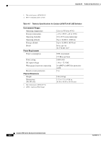
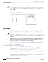
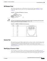
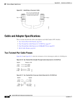
APPENDIX B Connectors and Cables This appendix describes the connectors, cables, and adapters that you use to connect the switch to other devices. Connector Specifications These sections describe the connectors used with the Catalyst 2950 switches and contains this information: • 10/100 Ports, page B-1 • 10/100/1000 Ports, page B-2 • 100BASE-FX and 1000BASE-SX Ports, page B-4 • LRE Port, page B-3 • GigaStack GBIC Module Ports, page B-4 • SFP Module Ports, page B-5 • Console Port, page B-5 10/100 Ports The 10/100 Ethernet ports use standard RJ-45 connectors and Ethernet pinouts with internal crossovers, as shown by an X in the port name. These ports have the transmit (TD) and receive (RD) signals internally crossed so that a twisted-pair straight-through cable and adapter can be attached to the port. Figure B-1 shows the pinout. When connecting 10/100 ports to other devices, such as servers, workstations, and routers, you can use a two or four twisted-pair, straight-through cable wired for 10BASE-T and 100BASE-TX. Figure B-10 shows the two twisted-pair, straight-through cable schematics. Figure B-12 shows the four twisted-pair, straight-through cable schematics. When connecting the ports to other devices, such as switches or repeaters, you can use a two or four twisted-pair, crossover cable. Figure B-11 shows the two twisted-pair, crossover cable schematics. Figure B-13 shows the four twisted-pair, crossover cable schematics. You can use Category 3, 4, or 5 cabling when connecting to 10BASE-T devices. You must use Category 5 cabling when connecting to 100BASE-TX devices. OL-6156-01 Catalyst 2950 Switch Hardware Installation Guide B-1
-
 1
1 -
2
-
3
-
4
-
5
-
6
-
7
-
8
-
9
-
10
-
11
-
12
-
13
-
14
-
15
-
16
-
17
-
18
-
19
-
20
-
21
-
22
-
23
-
24
-
25
-
26
-
27
-
28
-
29
-
30
-
31
-
32
-
33
-
34
-
35
-
36
-
37
-
38
-
39
-
40
-
41
-
42
-
43
-
44
-
45
-
46
-
47
-
48
-
49
-
50
-
51
-
52
-
53
-
54
-
55
-
56
-
57
-
58
-
59
-
60
-
61
-
62
-
63
-
64
-
65
-
66
-
67
-
68
-
69
-
70
-
71
-
72
-
73
-
74
-
75
-
76
-
77
-
78
-
79
-
80
-
81
-
82
-
83
-
84
-
85
-
86
-
87
-
88
-
89
-
90
-
91
-
92
-
93
-
 94
94 -
 95
95 -
 96
96 -
 97
97 -
 98
98 -
 99
99 -
 100
100 -
 101
101 -
 102
102 -
 103
103 -
 104
104 -
105
-
106
-
107
-
108
-
109
-
110
-
111
-
112
-
113
-
114
-
115
-
116
-
117
-
118
-
119
-
120
-
121
-
122
-
123
-
124
-
125
-
126
-
127
-
128
-
129
-
130
-
131
-
132
-
133
-
134
 |
 |