Cisco 2950 Hardware Installation Guide - Page 121
Taking Out What You Need, Connecting to the Console Port
 |
UPC - 746320454504
View all Cisco 2950 manuals
Add to My Manuals
Save this manual to your list of manuals |
Page 121 highlights
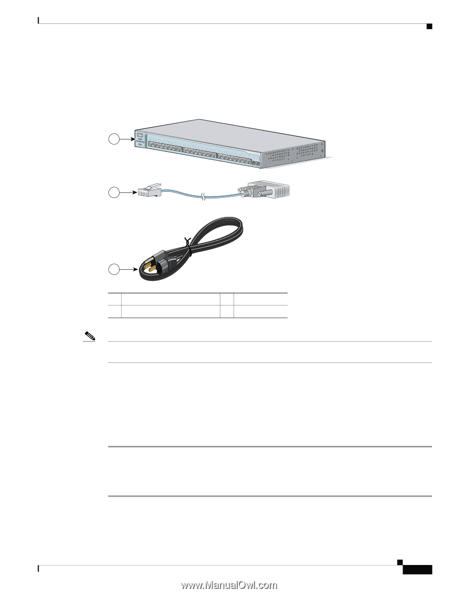
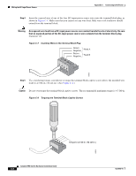
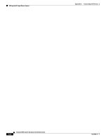
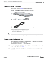
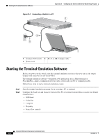
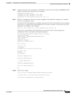
Appendix D Configuring the Switch with the CLI-Based Setup Program Taking Out What You Need Taking Out What You Need Remove the items shown in Figure D-1 from the shipping container: Figure D-1 Catalyst 2950 Switch, Adapter Cable, and AC Power Cord 1 SYST RPS STAT UTIL DUPLX SPEED MODE 1x 2x 3x 4x 5x 6x 7x 8x 9x 10x 11x 10BASE-T / 100BASE-TX 12x 13x 14x 15x 16x 17x 18x 19x 20x 21x 22x 23x Catalyst 2950 SERIES 24x 100BASE-FX 25 26 2 89367 3 1 Catalyst 2950 switch 3 AC power cord 2 RJ-45-to-DB-9 adapter cable Note You need to provide the Category 5 straight-through cables to connect the switch ports to other Ethernet devices. Connecting to the Console Port You can use the console port to perform the initial configuration. To connect the switch console port to a PC, use the supplied RJ-45-to-DB-9 adapter cable. Follow these steps to connect the PC or terminal to the switch: Step 1 Step 2 Using the supplied RJ-45-to-DB-9 adapter cable, insert the RJ-45 connector into the console port on the rear of a switch, as shown in Figure D-2. Attach the DB-9 female DTE of the adapter cable to a PC serial port, or attach an appropriate adapter to the terminal. OL-6156-01 Catalyst 2950 Switch Hardware Installation Guide D-3
-
 1
1 -
2
-
3
-
4
-
5
-
6
-
7
-
8
-
9
-
10
-
11
-
12
-
13
-
14
-
15
-
16
-
17
-
18
-
19
-
20
-
21
-
22
-
23
-
24
-
25
-
26
-
27
-
28
-
29
-
30
-
31
-
32
-
33
-
34
-
35
-
36
-
37
-
38
-
39
-
40
-
41
-
42
-
43
-
44
-
45
-
46
-
47
-
48
-
49
-
50
-
51
-
52
-
53
-
54
-
55
-
56
-
57
-
58
-
59
-
60
-
61
-
62
-
63
-
64
-
65
-
66
-
67
-
68
-
69
-
70
-
71
-
72
-
73
-
74
-
75
-
76
-
77
-
78
-
79
-
80
-
81
-
82
-
83
-
84
-
85
-
86
-
87
-
88
-
89
-
90
-
91
-
92
-
93
-
94
-
95
-
96
-
97
-
98
-
99
-
100
-
101
-
102
-
103
-
104
-
105
-
106
-
107
-
108
-
109
-
110
-
111
-
112
-
113
-
114
-
115
-
 116
116 -
 117
117 -
 118
118 -
 119
119 -
 120
120 -
 121
121 -
 122
122 -
 123
123 -
 124
124 -
 125
125 -
 126
126 -
127
-
128
-
129
-
130
-
131
-
132
-
133
-
134
 |
 |