Cisco 2950 Hardware Installation Guide - Page 23
Front-Panel Description - mode button
 |
UPC - 746320454504
View all Cisco 2950 manuals
Add to My Manuals
Save this manual to your list of manuals |
Page 23 highlights
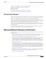
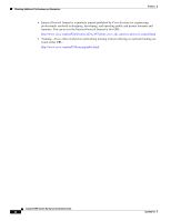
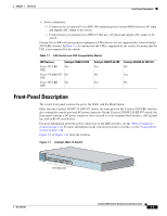
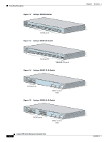
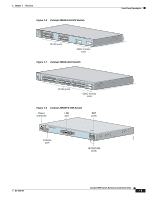
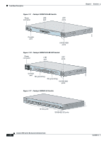
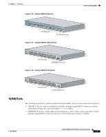
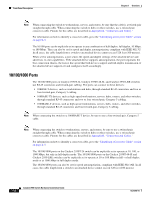
Chapter 1 Overview Front-Panel Description • Power redundancy - Connection for an optional Cisco RPS 300 redundant power system (RPS) that uses AC input and supplies DC output to the switch - Connection for an optional Cisco RPS 675 that uses AC input and supplies DC output to the switch Certain Cisco LRE customer premises equipment (CPE) devices are not supported by certain Catalyst 2950 LRE switches. In Table 1-1, Yes means that the CPE is supported by the switch; No means that the CPE is not supported by the switch. Table 1-1 LRE Switch and CPE Compatibility Matrix LRE Devices Catalyst 2950ST-8 LRE Cisco 575 LRE Yes CPE Cisco 576 LRE 997 No CPE Cisco 585 LRE Yes CPE Catalyst 2950ST-24 LRE Catalyst 2950ST-24 LRE 997 Yes No No Yes Yes No Front-Panel Description The switch front panel contains the ports, the LEDs, and the Mode button. Other than the Catalyst 2950ST-24 LRE 997 switch, the front panel of the Catalyst 2950 LRE switches also contain the console port and AC power connector. On the Catalyst 2950ST-24 LRE 997 switch, the front panel contains a DC power connector (also referred to as the terminal block header), a DC ground lug, and an RJ-45 console port. For more information about the power connectors on the LRE switches, see the "Power Connectors" section on page 1-22. For more information on the console port on these switches, see the "Console Port" section on page 1-24. Figure 1-1 to Figure 1-12 show the switches. Figure 1-1 Catalyst 2950-12 Switch 45568 SYST RPS STAT UTIL DUPLX SPEED MODE 1x 2x 3x 4x 5x 6x 7x 8x 9x 10x 11x 10Base-T / 100Base-TX 12x 10/100 ports Catalyst 2950 SERIES OL-6156-01 Catalyst 2950 Switch Hardware Installation Guide 1-3
-
 1
1 -
2
-
3
-
4
-
5
-
6
-
7
-
8
-
9
-
10
-
11
-
12
-
13
-
14
-
15
-
16
-
17
-
 18
18 -
 19
19 -
 20
20 -
 21
21 -
 22
22 -
 23
23 -
 24
24 -
 25
25 -
 26
26 -
 27
27 -
 28
28 -
29
-
30
-
31
-
32
-
33
-
34
-
35
-
36
-
37
-
38
-
39
-
40
-
41
-
42
-
43
-
44
-
45
-
46
-
47
-
48
-
49
-
50
-
51
-
52
-
53
-
54
-
55
-
56
-
57
-
58
-
59
-
60
-
61
-
62
-
63
-
64
-
65
-
66
-
67
-
68
-
69
-
70
-
71
-
72
-
73
-
74
-
75
-
76
-
77
-
78
-
79
-
80
-
81
-
82
-
83
-
84
-
85
-
86
-
87
-
88
-
89
-
90
-
91
-
92
-
93
-
94
-
95
-
96
-
97
-
98
-
99
-
100
-
101
-
102
-
103
-
104
-
105
-
106
-
107
-
108
-
109
-
110
-
111
-
112
-
113
-
114
-
115
-
116
-
117
-
118
-
119
-
120
-
121
-
122
-
123
-
124
-
125
-
126
-
127
-
128
-
129
-
130
-
131
-
132
-
133
-
134
 |
 |