Cisco 2950 Hardware Installation Guide - Page 123
Connecting to a Power Source, Entering the Initial Configuration Information, IP Settings
 |
UPC - 746320454504
View all Cisco 2950 manuals
Add to My Manuals
Save this manual to your list of manuals |
Page 123 highlights
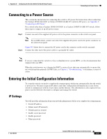
Appendix D Configuring the Switch with the CLI-Based Setup Program Connecting to a Power Source Connecting to a Power Source This section has instructions for connecting the switch to AC power. For instructions about connecting the Catalyst 2950G-24-EI-DC or Catalyst 2950ST-24 LRE 997 switch to DC power, see Appendix C, "Connecting to DC Power." For a switch other than a Catalyst 2950G-24-EI-DC or a Catalyst 2950ST-24 LRE 997 switch, follow these steps to connect to an AC power source: Step 1 Connect one end of the supplied AC power cord to the power connector on the switch rear panel. Note For an LRE switch, connect one end of the supplied AC power cord to the power connector on the switch front panel. Figure D-2 shows how to connect the AC power cord to the connector on the switch rear panel. Step 2 Connect the other end of the power cable to a grounded AC outlet. Note If you are connecting the switch to a Cisco redundant power system (RPS), see the documentation that shipped with your RPS. When the switch powers on, it begins the POST, a series of tests that runs automatically to ensure that the switch functions properly. If POST fails, see Chapter 3, "Troubleshooting," to determine a course of action. Entering the Initial Configuration Information To set up the switch, you need to complete the setup program, which runs automatically after the switch is powered on. You must assign an IP address and other configuration information necessary for the switch to communicate with the local routers and the Internet. This information is also required if you plan to use the Network Assistant to configure and manage the switch. IP Settings You will need this information from your network administrator before you complete the setup program: • Switch IP address • Subnet mask (IP netmask) • Default gateway (router) • Enable secret password • Enable password • Telnet password OL-6156-01 Catalyst 2950 Switch Hardware Installation Guide D-5
-
 1
1 -
2
-
3
-
4
-
5
-
6
-
7
-
8
-
9
-
10
-
11
-
12
-
13
-
14
-
15
-
16
-
17
-
18
-
19
-
20
-
21
-
22
-
23
-
24
-
25
-
26
-
27
-
28
-
29
-
30
-
31
-
32
-
33
-
34
-
35
-
36
-
37
-
38
-
39
-
40
-
41
-
42
-
43
-
44
-
45
-
46
-
47
-
48
-
49
-
50
-
51
-
52
-
53
-
54
-
55
-
56
-
57
-
58
-
59
-
60
-
61
-
62
-
63
-
64
-
65
-
66
-
67
-
68
-
69
-
70
-
71
-
72
-
73
-
74
-
75
-
76
-
77
-
78
-
79
-
80
-
81
-
82
-
83
-
84
-
85
-
86
-
87
-
88
-
89
-
90
-
91
-
92
-
93
-
94
-
95
-
96
-
97
-
98
-
99
-
100
-
101
-
102
-
103
-
104
-
105
-
106
-
107
-
108
-
109
-
110
-
111
-
112
-
113
-
114
-
115
-
116
-
117
-
 118
118 -
 119
119 -
 120
120 -
 121
121 -
 122
122 -
 123
123 -
 124
124 -
 125
125 -
 126
126 -
 127
127 -
 128
128 -
129
-
130
-
131
-
132
-
133
-
134
 |
 |
