Cisco 2950 Hardware Installation Guide - Page 66
Attaching the RPS Connector Cover, Stripping the Ground Wire, Step 1
 |
UPC - 746320454504
View all Cisco 2950 manuals
Add to My Manuals
Save this manual to your list of manuals |
Page 66 highlights
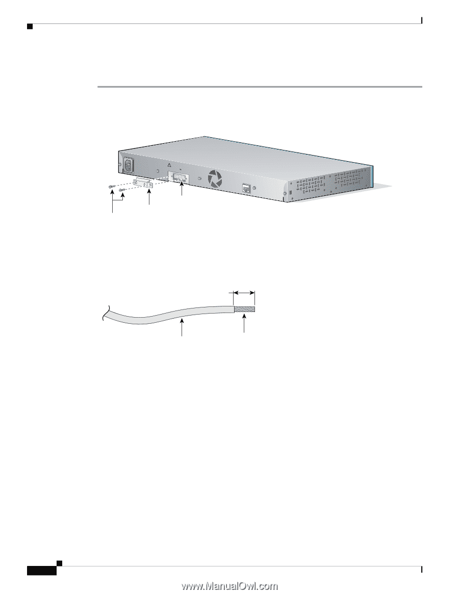
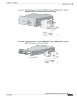
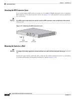
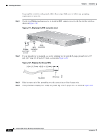
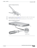
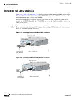
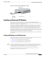
Installing the Switch Chapter 2 Installation To ground the switch to earth ground, follow these steps. Make sure to follow any grounding requirements at your site. Step 1 Use the two Phillips pan-head screws to attach the RPS connector cover to the back of the switch as shown in Figure 2-21. Figure 2-21 Attaching the RPS Connector Cover 111398 12005R@[email protected]~~ [email protected]. CONSOLE Step 2 Phillips pan-head screws RPS RPS connector connector cover If your ground wire is insulated, use a wire stripping tool to strip the 6-gauge ground wire to 0.5 inch (12.7 mm) ± 0.02 inch (0.5 mm), as shown in Figure 2-22. Figure 2-22 Stripping the Ground Wire 0.5 in. (12.7 mm) ± 0.02 in. (0.5 mm) 60528 Insulation Wire lead Step 3 Slide the open end of the ground lug over the exposed area of the 6-gauge wire. Step 4 Using a Panduit crimping tool, crimp the ground lug to the 6-gauge wire, as shown in Figure 2-23. 2-20 Catalyst 2950 Switch Hardware Installation Guide OL-6156-01
-
 1
1 -
2
-
3
-
4
-
5
-
6
-
7
-
8
-
9
-
10
-
11
-
12
-
13
-
14
-
15
-
16
-
17
-
18
-
19
-
20
-
21
-
22
-
23
-
24
-
25
-
26
-
27
-
28
-
29
-
30
-
31
-
32
-
33
-
34
-
35
-
36
-
37
-
38
-
39
-
40
-
41
-
42
-
43
-
44
-
45
-
46
-
47
-
48
-
49
-
50
-
51
-
52
-
53
-
54
-
55
-
56
-
57
-
58
-
59
-
60
-
 61
61 -
 62
62 -
 63
63 -
 64
64 -
 65
65 -
 66
66 -
 67
67 -
 68
68 -
 69
69 -
 70
70 -
 71
71 -
72
-
73
-
74
-
75
-
76
-
77
-
78
-
79
-
80
-
81
-
82
-
83
-
84
-
85
-
86
-
87
-
88
-
89
-
90
-
91
-
92
-
93
-
94
-
95
-
96
-
97
-
98
-
99
-
100
-
101
-
102
-
103
-
104
-
105
-
106
-
107
-
108
-
109
-
110
-
111
-
112
-
113
-
114
-
115
-
116
-
117
-
118
-
119
-
120
-
121
-
122
-
123
-
124
-
125
-
126
-
127
-
128
-
129
-
130
-
131
-
132
-
133
-
134
 |
 |