Cisco 2950 Hardware Installation Guide - Page 76
Connecting to an LRE Port, Connection Guidelines
 |
UPC - 746320454504
View all Cisco 2950 manuals
Add to My Manuals
Save this manual to your list of manuals |
Page 76 highlights
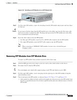
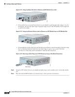
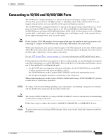
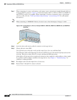
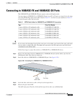
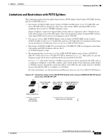
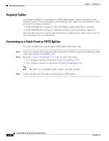
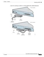
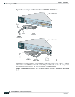
Connecting to an LRE Port Chapter 2 Installation Step 5 Step 6 The LED turns amber while STP discovers the network topology and searches for loops. This process takes about 30 seconds, and then the port LED turns green. If the LED is off, the target device might not be turned on, there might be a cable problem, or there might be a problem with the adapter installed in the target device. See Chapter 3, "Troubleshooting," for solutions to cabling problems. Reconfigure and restart the target device if necessary. Repeat Steps 1 through 5 to connect each port. Connecting to an LRE Port Depending on the switch model, you can connect the LRE port to up to 8 or up to 24 LRE customer premises equipment (CPE) devices through a patch panel. For information about which LRE CPE devices are supported by the LRE switches, see Table 1-1 on page 1-3. Note You can connect both Cisco 575 LRE CPE and Cisco 585 LRE CPE devices to your Catalyst 2950ST-8 LRE or Catalyst 2950ST-24 LRE switch. You can connect only the Cisco 576 LRE CPE 997 device to LRE ports on a Catalyst 2950ST-24 LRE 997 switch. You can hot swap the CPE devices without powering down the switch or disrupting the other switch ports. Connection Guidelines If telephone services, such as voice or Integrated Services Digital Network (ISDN), use the same cabling as the LRE traffic, you must connect the LRE to a plain old telephone service (POTS) splitter. The splitter routes LRE data (high-frequency) and voice (low-frequency) traffic from the telephone line to the switch and private branch exchange (PBX) switch or public switched telephone network (PSTN). If the other telephone services are connected through a PBX switch, you can use a Cisco LRE 48 POTS Splitter. The PBX routes voice traffic to private telephone networks and the PSTN. For more information about the Cisco LRE 48 POTS Splitter (PS-1M-LRE-48), see the Installation and Warranty Notes for the Cisco LRE 48 POTS Splitter. If the installation does not have a PBX, you need to use a homologated POTS splitter to connect to the PSTN. For more information about homologated POTS splitters, contact your Cisco sales representative. If a connection to a telephone network is not required, you do not need a splitter, and you can connect the switch to the patch panel. 2-30 Catalyst 2950 Switch Hardware Installation Guide OL-6156-01
-
 1
1 -
2
-
3
-
4
-
5
-
6
-
7
-
8
-
9
-
10
-
11
-
12
-
13
-
14
-
15
-
16
-
17
-
18
-
19
-
20
-
21
-
22
-
23
-
24
-
25
-
26
-
27
-
28
-
29
-
30
-
31
-
32
-
33
-
34
-
35
-
36
-
37
-
38
-
39
-
40
-
41
-
42
-
43
-
44
-
45
-
46
-
47
-
48
-
49
-
50
-
51
-
52
-
53
-
54
-
55
-
56
-
57
-
58
-
59
-
60
-
61
-
62
-
63
-
64
-
65
-
66
-
67
-
68
-
69
-
70
-
 71
71 -
 72
72 -
 73
73 -
 74
74 -
 75
75 -
 76
76 -
 77
77 -
 78
78 -
 79
79 -
 80
80 -
 81
81 -
82
-
83
-
84
-
85
-
86
-
87
-
88
-
89
-
90
-
91
-
92
-
93
-
94
-
95
-
96
-
97
-
98
-
99
-
100
-
101
-
102
-
103
-
104
-
105
-
106
-
107
-
108
-
109
-
110
-
111
-
112
-
113
-
114
-
115
-
116
-
117
-
118
-
119
-
120
-
121
-
122
-
123
-
124
-
125
-
126
-
127
-
128
-
129
-
130
-
131
-
132
-
133
-
134
 |
 |