Cisco 2950 Hardware Installation Guide - Page 36
System LED, RPS LED, Port Mode and Port Status LEDs, Color, System Status, RPS Status - fan
 |
UPC - 746320454504
View all Cisco 2950 manuals
Add to My Manuals
Save this manual to your list of manuals |
Page 36 highlights
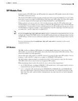
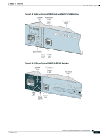
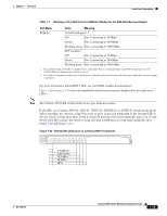
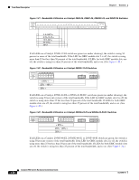
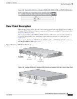
Front-Panel Description Chapter 1 Overview System LED The system LED shows whether the system is receiving power and functioning properly. Table 1-3 lists the LED colors and meanings. Table 1-3 System LED Color Off Green Amber System Status System is not powered up. System is operating normally. System is receiving power but is not functioning properly. For information about the system LED colors during the power-on self-test (POST), see the "Connecting to a Power Source" section on page D-5. RPS LED The RPS LED shows the RPS status. Table 1-4 lists the LED colors and meanings. Table 1-4 RPS LED Color RPS Status Off RPS is off or is not installed. Solid green RPS is connected and ready to provide back-up power. Flashing green RPS is connected but is unavailable because it is providing power to another device (redundancy has been allocated to a neighboring device). Solid amber RPS is in standby mode or in a fault condition. Press the Standby/Active button on the RPS, and the LED should turn green. If it does not, the RPS fan could have failed. Contact Cisco Systems. Flashing amber The internal power supply in a switch has failed, and the RPS is providing power to the switch (redundancy has been allocated to this device). For more information about the Cisco RPS 300, see the Cisco RPS 300 Redundant Power System Hardware Installation Guide. For more information about the Cisco RPS 675, see the Cisco RPS 675 Redundant Power System Hardware Installation Guide. Port Mode and Port Status LEDs To select or change the port mode, press the Mode button (see Figure 1-15 to Figure 1-18) to highlight the mode that you want. Release the button to enable the highlighted mode. Each port has a port status LED, also called a port LED. These LEDs, as a group or individually, display information about the switch and the individual ports. The port modes (see Table 1-5) determine the type of information displayed. 1-16 Catalyst 2950 Switch Hardware Installation Guide OL-6156-01
-
 1
1 -
2
-
3
-
4
-
5
-
6
-
7
-
8
-
9
-
10
-
11
-
12
-
13
-
14
-
15
-
16
-
17
-
18
-
19
-
20
-
21
-
22
-
23
-
24
-
25
-
26
-
27
-
28
-
29
-
30
-
 31
31 -
 32
32 -
 33
33 -
 34
34 -
 35
35 -
 36
36 -
 37
37 -
 38
38 -
 39
39 -
 40
40 -
 41
41 -
42
-
43
-
44
-
45
-
46
-
47
-
48
-
49
-
50
-
51
-
52
-
53
-
54
-
55
-
56
-
57
-
58
-
59
-
60
-
61
-
62
-
63
-
64
-
65
-
66
-
67
-
68
-
69
-
70
-
71
-
72
-
73
-
74
-
75
-
76
-
77
-
78
-
79
-
80
-
81
-
82
-
83
-
84
-
85
-
86
-
87
-
88
-
89
-
90
-
91
-
92
-
93
-
94
-
95
-
96
-
97
-
98
-
99
-
100
-
101
-
102
-
103
-
104
-
105
-
106
-
107
-
108
-
109
-
110
-
111
-
112
-
113
-
114
-
115
-
116
-
117
-
118
-
119
-
120
-
121
-
122
-
123
-
124
-
125
-
126
-
127
-
128
-
129
-
130
-
131
-
132
-
133
-
134
 |
 |