Cisco 2950 Hardware Installation Guide - Page 39
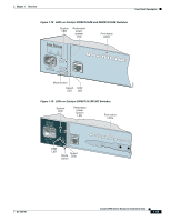
Bandwidth Utilization on Catalyst 2950-12 Switches, Table 1-7, Meaning of Port LED - syst led flash amber
 |
UPC - 746320454504
View all Cisco 2950 manuals
Add to My Manuals
Save this manual to your list of manuals |
Page 39 highlights
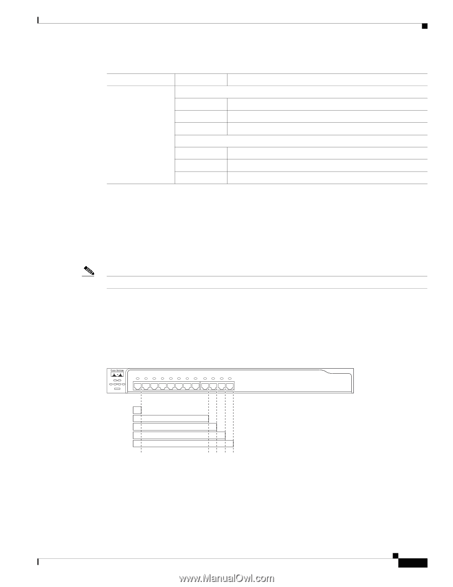
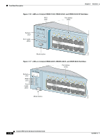
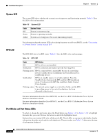
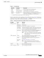
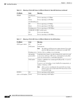
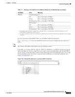
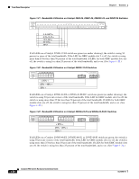
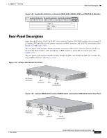
Chapter 1 Overview Front-Panel Description Table 1-7 Meaning of Port LED Colors in Different Modes for the LRE Switches (continued) Port Mode SPEED Color Meaning 10/100/1000 ports1 2 Off Port is operating at 10 Mbps. Green Port is operating at 100 Mbps. Flashing green Port is operating at 1000 Mbps. SFP modules1 2 Off Port is operating at 10 Mbps Green Port is operating at 100 Mbps Flashing green Port is operating at 1000 Mbps 1. On an LRE switch, the LEDs for Uplink Port 1 and Uplink Port 2 correspond either to the SFP module port or to the 10/100/1000 port, depending on which is active. 2. If an LRE switch senses connections to both ports, by default, the switch chooses the fiber-optic connection over the copper connection. For more information about GBIC LEDs, see your GBIC module documentation. Figure 1-20 to Figure 1-24 show the bandwidth utilization percentages displayed by the right-most LEDs. Note The Catalyst 2950 LRE switch LEDs do not give utilization status. If all LEDs on a Catalyst 2950-12, 2950-24, 2950C-24, 2950SX-24, or 2950T-24 switch are green (no amber showing), the switch is using 50 percent or more of the total bandwidth. If the far-right LED is off, the switch is using more than 25 but less than 50 percent of the total bandwidth, and so on. If only the far-left LED is green, the switch is using less than 0.0488 percent of the total bandwidth. (See Figure 1-20 and Figure 1-21.) Figure 1-20 Bandwidth Utilization on Catalyst 2950-12 Switches SYST RPS STAT UTIL DUPLX SPEED MODE 1x 2x 3x 4x 5x 6x 7x 8x 10Base-T / 100Base-TX 9x 10x 11x 12x Catalyst 2950 SERIES 47267 0-0.0487%+ 6.25-12.4%+ 12.5-24%+ 25-49%+ 50%+ OL-6156-01 Catalyst 2950 Switch Hardware Installation Guide 1-19
-
 1
1 -
2
-
3
-
4
-
5
-
6
-
7
-
8
-
9
-
10
-
11
-
12
-
13
-
14
-
15
-
16
-
17
-
18
-
19
-
20
-
21
-
22
-
23
-
24
-
25
-
26
-
27
-
28
-
29
-
30
-
31
-
32
-
33
-
 34
34 -
 35
35 -
 36
36 -
 37
37 -
 38
38 -
 39
39 -
 40
40 -
 41
41 -
 42
42 -
 43
43 -
 44
44 -
45
-
46
-
47
-
48
-
49
-
50
-
51
-
52
-
53
-
54
-
55
-
56
-
57
-
58
-
59
-
60
-
61
-
62
-
63
-
64
-
65
-
66
-
67
-
68
-
69
-
70
-
71
-
72
-
73
-
74
-
75
-
76
-
77
-
78
-
79
-
80
-
81
-
82
-
83
-
84
-
85
-
86
-
87
-
88
-
89
-
90
-
91
-
92
-
93
-
94
-
95
-
96
-
97
-
98
-
99
-
100
-
101
-
102
-
103
-
104
-
105
-
106
-
107
-
108
-
109
-
110
-
111
-
112
-
113
-
114
-
115
-
116
-
117
-
118
-
119
-
120
-
121
-
122
-
123
-
124
-
125
-
126
-
127
-
128
-
129
-
130
-
131
-
132
-
133
-
134
 |
 |