Cisco 2950 Hardware Installation Guide - Page 29
BASE-FX and 1000BASE-SX Ports, LRE Port
 |
UPC - 746320454504
View all Cisco 2950 manuals
Add to My Manuals
Save this manual to your list of manuals |
Page 29 highlights
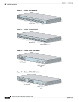
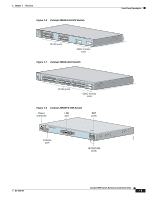
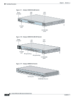
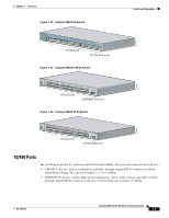
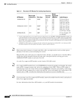
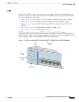
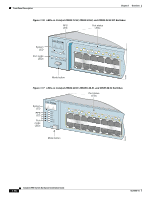
Chapter 1 Overview Front-Panel Description Note On the Catalyst 2950 LRE switches, the four input uplink ports are bundled as two logical ports, each consisting of a copper 10/100/1000 port and a fiber-optic SFP module slot, respectively. Within each logical port, you can use only the copper or the fiber-optic port at one time. If a Catalyst 2950 LRE switch senses more than two connections for both logical ports, the switch chooses the fiber-optic connections over the copper connections in default operation. See the "SFP Module Slots" section on page 1-11 for more information on LRE uplink logical ports. 100BASE-FX and 1000BASE-SX Ports The 100BASE-FX and 1000BASE-SX ports both use 50/125- or 62.5/125-micron multimode fiber-optic cabling. The 100BASE-FX ports operate only at 100 Mbps in full-duplex mode, and the 1000BASE-SX ports operate only at 1000 Mbps in full-duplex mode. In full-duplex mode, the cable length from a 100BASE-FX port on a switch to an attached device cannot exceed 6562 feet (2 kilometers). The cable length from a 1000BASE-SX port on a switch to an attached device cannot exceed 1804 feet (550 meters). You can connect a 100BASE-FX or 1000BASE-SX port to an SC or ST port on a target device by using one of the MT-RJ fiber-optic patch cables listed in Table 2-1 on page 2-29. Use the Cisco part numbers in Table 2-1 to order the patch cables that you need. LRE Port The LRE port (shown in Figure 1-8) uses one RJ-21 connector to connect up to 24 Cisco LRE CPE devices through structured or unstructured wiring, such as existing telephone lines. The link between the LRE switch port and each CPE device can reach speeds of up to 15 Mbps (full duplex) over distances of up to 4921 feet (1500 meters). Certain Catalyst 2950 LRE switches support certain Cisco LRE CPE devices. Table 1-1 on page 1-3 shows which LRE switches support which CPE devices. You can connect the Cisco 575 LRE CPE and Cisco 585 LRE CPE devices to LRE ports on the same Catalyst 2950ST-8 LRE or 2950ST-24 LRE switch. You can connect the Cisco 576 LRE CPE 997 device only to LRE ports on a Catalyst 2950ST-24 LRE 997 switch. You can hot swap the CPE devices without powering down the switch or disrupting the other switch ports. The default mode for each LRE port is speed autosensing and half-duplex operation. For information about configuring the LRE ports, see the switch software configuration guide. If telephone services, such as voice or an Integrated Services Digital Network (ISDN), use the same cabling as LRE traffic, the LRE port must be connected to the patch panel through a plain old telephone service (POTS) splitter. The splitter routes LRE data (high-frequency) and voice (low-frequency) traffic from the telephone line to the switch and private branch exchange (PBX) switch or public switched telephone network (PSTN). If the other telephone services are connected through a PBX switch, a non-homologated POTS splitter, such as the Cisco LRE 48 POTS Splitter, can be used. The PBX routes voice traffic to private telephone networks and the PSTN. For more information about the Cisco LRE 48 POTS Splitter (PS-1M-LRE-48), see the Installation and Warranty Notes for the Cisco LRE 48 POTS Splitter. OL-6156-01 Catalyst 2950 Switch Hardware Installation Guide 1-9
-
 1
1 -
2
-
3
-
4
-
5
-
6
-
7
-
8
-
9
-
10
-
11
-
12
-
13
-
14
-
15
-
16
-
17
-
18
-
19
-
20
-
21
-
22
-
23
-
 24
24 -
 25
25 -
 26
26 -
 27
27 -
 28
28 -
 29
29 -
 30
30 -
 31
31 -
 32
32 -
 33
33 -
 34
34 -
35
-
36
-
37
-
38
-
39
-
40
-
41
-
42
-
43
-
44
-
45
-
46
-
47
-
48
-
49
-
50
-
51
-
52
-
53
-
54
-
55
-
56
-
57
-
58
-
59
-
60
-
61
-
62
-
63
-
64
-
65
-
66
-
67
-
68
-
69
-
70
-
71
-
72
-
73
-
74
-
75
-
76
-
77
-
78
-
79
-
80
-
81
-
82
-
83
-
84
-
85
-
86
-
87
-
88
-
89
-
90
-
91
-
92
-
93
-
94
-
95
-
96
-
97
-
98
-
99
-
100
-
101
-
102
-
103
-
104
-
105
-
106
-
107
-
108
-
109
-
110
-
111
-
112
-
113
-
114
-
115
-
116
-
117
-
118
-
119
-
120
-
121
-
122
-
123
-
124
-
125
-
126
-
127
-
128
-
129
-
130
-
131
-
132
-
133
-
134
 |
 |
