Cisco 2950 Hardware Installation Guide - Page 42
Power Connectors, Internal Power Supply Connector - fan install
 |
UPC - 746320454504
View all Cisco 2950 manuals
Add to My Manuals
Save this manual to your list of manuals |
Page 42 highlights
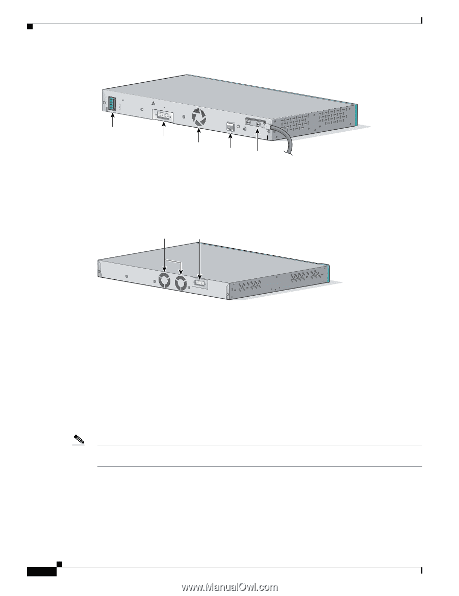
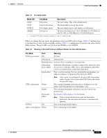
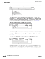
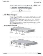
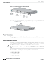
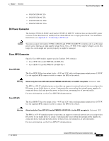
Rear-Panel Description Figure 1-27 Catalyst 2950G-24-EI-DC Switch Rear Panel Chapter 1 Overview 65291 36 1 - 72V 0.5A A B DC power connector [email protected]. CONSOLE RPS connector Fan RJ-45 console port DC ground lug Figure 1-28 Catalyst 2950ST-8 LRE Switch, Catalyst 2950ST-24 LRE, and Catalyst 2950ST-24 LRE 997 Switch Rear Panel RPS Fans connector 81225 Power Connectors You can provide power to a switch by using the AC internal power supply, the DC-input power source, or the Cisco RPS. Internal Power Supply Connector The internal AC power supply is an autoranging unit that supports input voltages between 100 and 240 VAC. Other than for the Catalyst 2950G-24-EI-DC and the Catalyst 2950ST-24 LRE 997 switches, use the supplied AC power cord to connect the AC power connector to an AC power outlet. Note The AC power connector is on the front panel of the Catalyst 2950ST-8 LRE and Catalyst 2950ST-24 LRE switches. You can order these L-shaped AC power cords from your Cisco sales representative: • CAB-NP1200-AC-AR= • CAB-NP1200-AC-AU= • CAB-NP1200-AC-CH= • CAB-NP1200-AC-EU= 1-22 Catalyst 2950 Switch Hardware Installation Guide OL-6156-01
-
 1
1 -
2
-
3
-
4
-
5
-
6
-
7
-
8
-
9
-
10
-
11
-
12
-
13
-
14
-
15
-
16
-
17
-
18
-
19
-
20
-
21
-
22
-
23
-
24
-
25
-
26
-
27
-
28
-
29
-
30
-
31
-
32
-
33
-
34
-
35
-
36
-
 37
37 -
 38
38 -
 39
39 -
 40
40 -
 41
41 -
 42
42 -
 43
43 -
 44
44 -
 45
45 -
 46
46 -
 47
47 -
48
-
49
-
50
-
51
-
52
-
53
-
54
-
55
-
56
-
57
-
58
-
59
-
60
-
61
-
62
-
63
-
64
-
65
-
66
-
67
-
68
-
69
-
70
-
71
-
72
-
73
-
74
-
75
-
76
-
77
-
78
-
79
-
80
-
81
-
82
-
83
-
84
-
85
-
86
-
87
-
88
-
89
-
90
-
91
-
92
-
93
-
94
-
95
-
96
-
97
-
98
-
99
-
100
-
101
-
102
-
103
-
104
-
105
-
106
-
107
-
108
-
109
-
110
-
111
-
112
-
113
-
114
-
115
-
116
-
117
-
118
-
119
-
120
-
121
-
122
-
123
-
124
-
125
-
126
-
127
-
128
-
129
-
130
-
131
-
132
-
133
-
134
 |
 |