Cisco 2950 Hardware Installation Guide - Page 85
Connecting to 1000BASE-T SFP Modules, Connecting to a Fiber-Optic SFP Module Port
 |
UPC - 746320454504
View all Cisco 2950 manuals
Add to My Manuals
Save this manual to your list of manuals |
Page 85 highlights
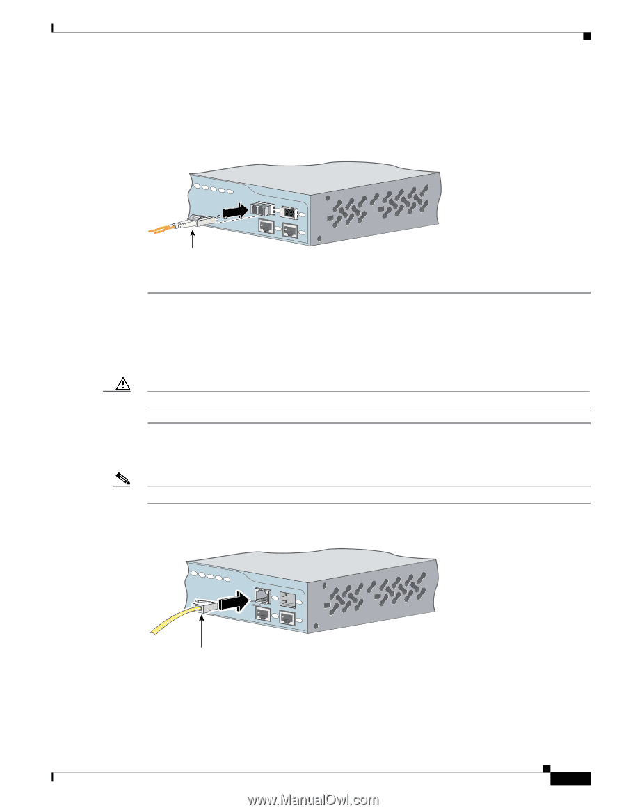
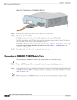
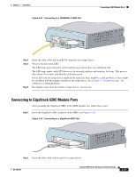
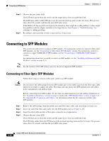
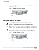
Chapter 2 Installation Connecting to SFP Modules If the LED is off, the target device might not be turned on, there might be a cable problem, or there might be problem with the adapter installed in the target device. See Chapter 3, "Troubleshooting," for solutions to cabling problems. Figure 2-43 Connecting to a Fiber-Optic SFP Module Port 81568 19 20 21 22 23 24 Cable Catalyst 2950 SERIES LRE 1 2 1 2 Step 5 If necessary, reconfigure and restart the switch or target device. Connecting to 1000BASE-T SFP Modules Follow these steps to connect a Category 5 cable to a 1000BASE-T SFP module: Caution To prevent ESD damage, follow your normal board and component handling procedures. Step 1 When connecting to servers, workstations, and routers, insert a four twisted-pair, straight-through cable in the RJ-45 connector. When connecting to switches or repeaters, insert a four twisted-pair, crossover cable. Note When connecting to a 1000BASE-T device, be sure to use a four twisted-pair, Category 5 cable. Figure 2-44 Connecting to a 1000BASE-T SFP Module 19 20 21 22 23 24 Catalyst 2950 SERIES LRE 1 2 1 2 97631 RJ-45 cable Step 2 Step 3 Insert the other cable end in an RJ-45 connector on a target device. Observe the port status LED. The LED turns green when the switch and the target device have an established link. OL-6156-01 Catalyst 2950 Switch Hardware Installation Guide 2-39
-
 1
1 -
2
-
3
-
4
-
5
-
6
-
7
-
8
-
9
-
10
-
11
-
12
-
13
-
14
-
15
-
16
-
17
-
18
-
19
-
20
-
21
-
22
-
23
-
24
-
25
-
26
-
27
-
28
-
29
-
30
-
31
-
32
-
33
-
34
-
35
-
36
-
37
-
38
-
39
-
40
-
41
-
42
-
43
-
44
-
45
-
46
-
47
-
48
-
49
-
50
-
51
-
52
-
53
-
54
-
55
-
56
-
57
-
58
-
59
-
60
-
61
-
62
-
63
-
64
-
65
-
66
-
67
-
68
-
69
-
70
-
71
-
72
-
73
-
74
-
75
-
76
-
77
-
78
-
79
-
 80
80 -
 81
81 -
 82
82 -
 83
83 -
 84
84 -
 85
85 -
 86
86 -
 87
87 -
 88
88 -
 89
89 -
 90
90 -
91
-
92
-
93
-
94
-
95
-
96
-
97
-
98
-
99
-
100
-
101
-
102
-
103
-
104
-
105
-
106
-
107
-
108
-
109
-
110
-
111
-
112
-
113
-
114
-
115
-
116
-
117
-
118
-
119
-
120
-
121
-
122
-
123
-
124
-
125
-
126
-
127
-
128
-
129
-
130
-
131
-
132
-
133
-
134
 |
 |