IBM 8840 Hardware Maintenance Manual
IBM 8840 - eServer xSeries 346 Manual
 |
UPC - 000435863799
View all IBM 8840 manuals
Add to My Manuals
Save this manual to your list of manuals |
IBM 8840 manual content summary:
- IBM 8840 | Hardware Maintenance Manual - Page 1
xSeries 346 Types 8840 and 1880 Hardware Maintenance Manual and Troubleshooting Guide - IBM 8840 | Hardware Maintenance Manual - Page 2
- IBM 8840 | Hardware Maintenance Manual - Page 3
xSeries 346 Types 8840 and 1880 Hardware Maintenance Manual and Troubleshooting Guide - IBM 8840 | Hardware Maintenance Manual - Page 4
Note: Before using this information and the product it supports, read the general information in Appendix B, "Safety information," on page 117. 10th Edition (March 2006) © . US Government Users Restricted Rights - Use, duplication or disclosure restricted by GSA ADP Schedule Contract with IBM Corp. - IBM 8840 | Hardware Maintenance Manual - Page 5
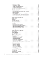
troubleshooting chart 21 Ethernet controller messages 21 Chapter 4. Installing options 23 Installation guidelines 23 System reliability guidelines 24 Working inside the server with the power on 24 Handling static-sensitive devices 25 Major components of the xSeries 346 Type 8640 server - IBM 8840 | Hardware Maintenance Manual - Page 6
symptoms 96 ServerGuide error symptoms 97 Software error symptoms 98 Power-supply LED errors 99 Service processor error codes 99 SCSI error codes 99 Temperature error messages 100 Fan error messages 101 iv xSeries 346 Types 8840 and 1880: Hardware Maintenance Manual and Troubleshooting Guide - IBM 8840 | Hardware Maintenance Manual - Page 7
self test (BIST 103 Bus fault messages 103 Undetermined problems 103 Problem determination tips 104 Chapter 7. Parts listing xSeries 346 Types 8840 and 1880 107 System 108 System replaceable units 109 Keyboard CRUs 112 Power cords 113 Appendix A. Getting help and technical assistance 115 - IBM 8840 | Hardware Maintenance Manual - Page 8
vi xSeries 346 Types 8840 and 1880: Hardware Maintenance Manual and Troubleshooting Guide - IBM 8840 | Hardware Maintenance Manual - Page 9
xSeries® 346 Types 8840 and 1880 2-U1 -high server. Important: The field replaceable unit (FRU) procedures in this document are intended for trained servicers who are familiar with IBM® products. Customer replacement units (CRUs) can be replaced by the customer. See Chapter 7, "Parts listing xSeries - IBM 8840 | Hardware Maintenance Manual - Page 10
Online support You can download the most current diagnostic, BIOS flash, and device-driver files from http://www.ibm.com/support. viii xSeries 346 Types 8840 and 1880: Hardware Maintenance Manual and Troubleshooting Guide - IBM 8840 | Hardware Maintenance Manual - Page 11
to this Hardware Maintenance Manual and Troubleshooting Guide, the following xSeries 346 Types 8840 and 1880 documentation is provided with your server: v Installation Guide This printed document contains setup and installation instructions. v Rack Installation Instructions This printed document - IBM 8840 | Hardware Maintenance Manual - Page 12
problem situations. v Attention: These notices indicate possible damage to programs, devices, or data. An attention notice is placed just before the instruction extremely hazardous procedure step or situation. 2 xSeries 346 Types 8840 and 1880: Hardware Maintenance Manual and Troubleshooting Guide - IBM 8840 | Hardware Maintenance Manual - Page 13
or "U." A 1-U-high device is 1.75 inches tall. Table 1. Features and specifications Microprocessor: Hot-swap power supplies: Acoustical noise emissions: v Intel® Xeon 2.8 GHz or higher v Declared sound power, idle: 6.6 bel depending on server model 625 watts (100-240 V ac) v Declared sound - IBM 8840 | Hardware Maintenance Manual - Page 14
the light path diagnostics panel. v System-error LED: When this LED is lit, it indicates that a system error has occurred. An LED on the light path diagnostics panel is also lit to help isolate the error. 4 xSeries 346 Types 8840 and 1880: Hardware Maintenance Manual and Troubleshooting Guide - IBM 8840 | Hardware Maintenance Manual - Page 15
locate the server among other servers. You can use IBM Director to light this LED remotely. v SCSI activity LED: When this LED is lit, it indicates that there is activity on the SCSI or IDE bus. v Power-control button: Press this button to turn the server on and off manually. A power-control-button - IBM 8840 | Hardware Maintenance Manual - Page 16
Approximately 5 seconds after the server is connected to ac power, the power-control button becomes active, and you can turn on the server and start the operating system by pressing the power-control button. 6 xSeries 346 Types 8840 and 1880: Hardware Maintenance Manual and Troubleshooting Guide - IBM 8840 | Hardware Maintenance Manual - Page 17
an orderly shutdown of the operating system and turn off the server, if your operating system supports this feature. v If the operating system stops functioning, you can press and hold the power-control button for more than 4 seconds to turn off the server. v The service processor can turn off the - IBM 8840 | Hardware Maintenance Manual - Page 18
8 xSeries 346 Types 8840 and 1880: Hardware Maintenance Manual and Troubleshooting Guide - IBM 8840 | Hardware Maintenance Manual - Page 19
driver files are available at http://www.ibm.com/support. The following configuration programs and capabilities come with the server: v Configuration/Setup Utility The Configuration/Setup Utility program is part of the basic input/output system (BIOS) code in your server to update the firmware and - IBM 8840 | Hardware Maintenance Manual - Page 20
program: 1. Turn on the server. 2. When the prompt Press F1 for Configuration/Setup appears, press F1. If you have set both a power-on password and an administrator . 3. Select settings to view or change. 10 xSeries 346 Types 8840 and 1880: Hardware Maintenance Manual and Troubleshooting Guide - IBM 8840 | Hardware Maintenance Manual - Page 21
" on page 13. 4. If the server is suspended and no error message is displayed, see "Error symptoms" on page 90 and "Undetermined problems" on page 103. 5. For information about power-supply problems, see "Power checkout" on page 19. 6. For intermittent problems, check the error logs; see "Diagnostic - IBM 8840 | Hardware Maintenance Manual - Page 22
-to-FRU index This index list problem symptoms, error codes, and steps to correct the problems. See Chapter 6, "Symptom-to-FRU index," on page 73 for more information. v Diagnostic programs and error messages 12 xSeries 346 Types 8840 and 1880: Hardware Maintenance Manual and Troubleshooting Guide - IBM 8840 | Hardware Maintenance Manual - Page 23
of the options installed in the server. This series of tests is called the power-on self-test, or POST. If POST finishes without detecting any problems, a single beep sounds, and the first screen of your operating system or application program appears. If POST detects a problem, more than one beep - IBM 8840 | Hardware Maintenance Manual - Page 24
you run the diagnostic programs. 2. If diagnostic error codes appear that are not listed in the tables, make sure that the server has the latest levels of BIOS, service processor, and ServeRAID code installed. 14 xSeries 346 Types 8840 and 1880: Hardware Maintenance Manual and Troubleshooting Guide - IBM 8840 | Hardware Maintenance Manual - Page 25
appears, select the test you want to run from the list that appears; then, follow the instructions on the screen. Notes: a. You can press F1 If the server stops during testing and you cannot continue, restart the server and try running the diagnostic programs again. If the problem remains, replace - IBM 8840 | Hardware Maintenance Manual - Page 26
diagnostics" on page 18. Power-on password override Power-on password override. Changing the position of this switch bypasses the power-on password check the next time the server is turned on and starts the 16 xSeries 346 Types 8840 and 1880: Hardware Maintenance Manual and Troubleshooting Guide - IBM 8840 | Hardware Maintenance Manual - Page 27
) For more information about power supply LEDs, see "Power-supply LED errors" on page 99. Light path diagnostics Use light path diagnostics to diagnose system errors. The light path diagnostics panel is inside the light path diagnostics drawer, on the right front of the server. To access the light - IBM 8840 | Hardware Maintenance Manual - Page 28
all power cords and external cables. 2. Remove the server cover. See "Removing the cover" on page 28 for more information. 3. Locate the flash boot block recovery jumper block (J60) on the system board. 18 xSeries 346 Types 8840 and 1880: Hardware Maintenance Manual and Troubleshooting Guide - IBM 8840 | Hardware Maintenance Manual - Page 29
diskette into the diskette drive. 6. Reinstall the server cover; then, reconnect all power cords. 7. Restart the server. The system begins the power-on self test (POST). 8. Select 1 - Update POST/BIOS from the menu that contains various flash update options. 9. When prompted as to whether you - IBM 8840 | Hardware Maintenance Manual - Page 30
server are using the same protocol. v Test the Ethernet controller. The way the Ethernet controller is tested depends on which operating system you are using (see the Ethernet controller device driver readme files). 20 xSeries 346 Types 8840 and 1880: Hardware Maintenance Manual and Troubleshooting - IBM 8840 | Hardware Maintenance Manual - Page 31
chart Use the following troubleshooting chart to find solutions to 10/100/1000 Mbps Ethernet controller problems that have definite symptoms. Description FRU/action The server stops running when loading device drivers. The PCI BIOS interrupt settings are incorrect. v Determine whether - IBM 8840 | Hardware Maintenance Manual - Page 32
22 xSeries 346 Types 8840 and 1880: Hardware Maintenance Manual and Troubleshooting Guide - IBM 8840 | Hardware Maintenance Manual - Page 33
25 Major components of the xSeries 346 Type 8640 server 26 Removing the cover 28 Removing the air baffle 29 Working with adapters 30 Installing a hot-swap drive 38 Installing memory modules 39 Installing a microprocessor 42 Installing a hot-swap power supply 47 Replacing a hot-swap fan - IBM 8840 | Hardware Maintenance Manual - Page 34
instructions for removing or installing a specific hot-swap component for any additional procedures that you might have to perform before you remove or install the component. v For a list of supported options for the server, go to http://www.ibm.com/servers/ eserver/serverproven/compat/us/ . System - IBM 8840 | Hardware Maintenance Manual - Page 35
device where others can handle and damage it. v While the device is still in its static-protective package, touch it to an unpainted metal part of the server for at least 2 seconds. This drains static electricity from the package and from your body. v Remove the device from its package and install - IBM 8840 | Hardware Maintenance Manual - Page 36
on hot-swap components.) See the instructions for removing or installing a specific hot-swap component for any additional procedures that you might have to perform before you remove or install the component. 26 xSeries 346 Types 8840 and 1880: Hardware Maintenance Manual and Troubleshooting Guide - IBM 8840 | Hardware Maintenance Manual - Page 37
differ slightly from your hardware. Hot-swap fans Fan guide assembly Microprocessor Ultra-slim hard disk drive tray Filler panel for drive bay PCI riser-card cage PCI low-profile-card cage VRM Heat sink Air baffle Microprocessor baffle Memory module System board Chapter 4. Installing options 27 - IBM 8840 | Hardware Maintenance Manual - Page 38
: For proper cooling and airflow, replace the cover before turning on the server. Operating the server for extended periods of time (over 30 minutes) with the cover removed might damage server components. 28 xSeries 346 Types 8840 and 1880: Hardware Maintenance Manual and Troubleshooting Guide - IBM 8840 | Hardware Maintenance Manual - Page 39
the air baffle to access certain components or connectors on the system board. The following illustration shows how to remove the air baffle 23. 2. Turn off the server and peripheral devices and disconnect all power cords and external cables (see "Turning off the server" on page 7); then, remove - IBM 8840 | Hardware Maintenance Manual - Page 40
retainer bracket; then, press the card in the connector and make sure that all tabs on the latch bracket secure the card in place. 30 xSeries 346 Types 8840 and 1880: Hardware Maintenance Manual and Troubleshooting Guide - IBM 8840 | Hardware Maintenance Manual - Page 41
SCSI cable is required if you are installing the ServeRAID-7k. - The ServeRAID-7k can be installed only in a dedicated slot on the system board. Attention: To avoid breaking the retaining clips or damaging the connectors, handle the clips gently. The following illustration shows how to install the - IBM 8840 | Hardware Maintenance Manual - Page 42
on page 23. 2. Turn off the server and peripheral devices and disconnect all power cords and external cables (see "Turning off the server" on page 7); then, remove the cover cage. PCI low-profilecard cage Latch 32 xSeries 346 Types 8840 and 1880: Hardware Maintenance Manual and Troubleshooting Guide - IBM 8840 | Hardware Maintenance Manual - Page 43
If you are installing an adapter in PCI slot 3 or 4, remove the PCI riser-card cage. Retention latch PCI riser-card cage 5. Slide the expansion-slot cover out of the PCI low-profile-card cage or PCI riser-card cage. Chapter 4. Installing options 33 - IBM 8840 | Hardware Maintenance Manual - Page 44
6. Install the adapter. The following illustration shows how to install an adapter in the PCI low-profile-card cage. PCI adapter 34 xSeries 346 Types 8840 and 1880: Hardware Maintenance Manual and Troubleshooting Guide - IBM 8840 | Hardware Maintenance Manual - Page 45
The following illustration shows how to install an adapter in the PCI riser-card cage. PCI adapter 7. If you removed the PCI low-profile-card cage to install the adapter, press the PCI low-profile-card cage firmly into the connector until the retention latch locks. Chapter 4. Installing options 35 - IBM 8840 | Hardware Maintenance Manual - Page 46
riser-card cage firmly into the connector and close the latch. Retention latch PCI riser-card cage 8. Connect any needed cables to the adapter. 36 xSeries 346 Types 8840 and 1880: Hardware Maintenance Manual and Troubleshooting Guide - IBM 8840 | Hardware Maintenance Manual - Page 47
top of components under the PCI riser-card cage or the PCI low-profile-card cage. v Make sure that cables are not pinched by the server components. The following illustration shows the cable routing for an adapter installed in the PCI low-profile-card cage. Note: Remove the PCI riser-card - IBM 8840 | Hardware Maintenance Manual - Page 48
cause all drives to operate at the lower throughput speed. v The SCSI ID that is assigned to each bay is printed on the server front. The following illustration shows how to install a hot-swap hard disk drive. 38 xSeries 346 Types 8840 and 1880: Hardware Maintenance Manual and Troubleshooting Guide - IBM 8840 | Hardware Maintenance Manual - Page 49
). b. Align the drive assembly with the guide rails in the bay. c. Gently push system memory. The server supports up to eight 1.8 V, 240-pin, PC2-3200, ECC DDR II SDRAM, 200 MHz DIMMs. Go to the ServerProven® list at http://www.ibm.com/servers/eserver/serverproven/compat/us/ for a list of memory - IBM 8840 | Hardware Maintenance Manual - Page 50
. See Table 5 for the online-spare memory DIMM connector assignments. Table 5. Online-spare memory DIMM connector assignments Active DIMM connectors Online-spare memory DIMM connectors 1 and 2 3 and 4 40 xSeries 346 Types 8840 and 1880: Hardware Maintenance Manual and Troubleshooting Guide - IBM 8840 | Hardware Maintenance Manual - Page 51
, the server configuration information changes. When you restart the server, the system displays a message indicating that the memory configuration has Turn off the server and disconnect all power cords and external cables (see "Turning off the server" on page 7); then, remove the server cover (see - IBM 8840 | Hardware Maintenance Manual - Page 52
the latest level of BIOS code and many other code updates for your server at http://www.ibm.com/support/. v (Optional) Obtain an SMP-capable operating system. For a list of supported operating systems and other options, go to http://www.ibm.com/servers/eserver/ serverproven/compat/us/. v To order - IBM 8840 | Hardware Maintenance Manual - Page 53
number of your server or computer v Do not remove the first microprocessor from the system board to install the second microprocessor. The following illustration is a simplified layout of the microprocessor connector locations and other microprocessor-related components on the system board. VRM (J72 - IBM 8840 | Hardware Maintenance Manual - Page 54
heat-sink socket; then, lift it off the heat-sink socket and store it in a safe place. 6. Install a VRM in the VRM connector (J72). 44 xSeries 346 Types 8840 and 1880: Hardware Maintenance Manual and Troubleshooting Guide - IBM 8840 | Hardware Maintenance Manual - Page 55
containing the microprocessor to any unpainted metal surface on the server. Then, remove the microprocessor from the package. b. Remove might result in permanent damage to the microprocessor, microprocessor socket, and system board. c. Rotate the locking lever on the microprocessor socket from - IBM 8840 | Hardware Maintenance Manual - Page 56
is in the open position. c. Align the heat sink above the microprocessor with the thermal grease side down. Press firmly on the heat sink. 46 xSeries 346 Types 8840 and 1880: Hardware Maintenance Manual and Troubleshooting Guide - IBM 8840 | Hardware Maintenance Manual - Page 57
, go to "Completing the installation" on page 51. Installing a hot-swap power supply The server supports a maximum of two hot-swap power supplies. Statement 8 CAUTION: Never remove the cover on a power supply or any part that has the following label attached. Hazardous voltage, current, and energy - IBM 8840 | Hardware Maintenance Manual - Page 58
on the power supply. The following illustration shows the power-supply connectors on the back of the server. Power supply 2 power cord connector Power supply 1 power cord connector TX/RX LINK TX/RX LINK 48 xSeries 346 Types 8840 and 1880: Hardware Maintenance Manual and Troubleshooting Guide - IBM 8840 | Hardware Maintenance Manual - Page 59
power supply is operating correctly. Replacing a hot-swap fan The following notes describe information that you must consider when installing a hot-swap fan. Attention: To ensure proper server operation, if a fan fails, replace it as soon as possible. v The server supports proper system cooling, - IBM 8840 | Hardware Maintenance Manual - Page 60
). 4. Remove the air baffle (see "Removing the air baffle" on page 29). 5. Disconnect any internal cables, as necessary. 6. Locate the battery (connector BH1) on the system board. 50 xSeries 346 Types 8840 and 1880: Hardware Maintenance Manual and Troubleshooting Guide - IBM 8840 | Hardware Maintenance Manual - Page 61
external cables and all power cords. 11. Reinstall the air baffle. 12. Reinstall the server cover (see "Completing the installation"). 13. Start the Configuration/Setup Utility program and set configuration parameters as needed. See the User's Guide on the IBM xSeries Documentation CD for additional - IBM 8840 | Hardware Maintenance Manual - Page 62
located under the air baffle. Connecting the cables Notes: 1. You must turn off the server (see "Turning off the server" on page 7) before connecting any cables to or disconnecting any cables from the server. 52 xSeries 346 Types 8840 and 1880: Hardware Maintenance Manual and Troubleshooting Guide - IBM 8840 | Hardware Maintenance Manual - Page 63
you can save the new configuration settings. For more information, see the section about configuring the server in the User's Guide on the IBM xSeries Documentation CD. Some options have device drivers that you must install. See the documentation that comes with each option for information about - IBM 8840 | Hardware Maintenance Manual - Page 64
connectors" on page 56 for information about SCSI cabling and SCSI IDs. Power-cage card internal cable connectors The following illustration shows the internal connectors on the power-cage card. Fan 3 Fan 9 54 xSeries 346 Types 8840 and 1880: Hardware Maintenance Manual and Troubleshooting Guide - IBM 8840 | Hardware Maintenance Manual - Page 65
pointing device) v Three Ethernet (one for remote server management using network, RJ-45) v Two Advanced Systems Management (ASM) v One keyboard v One Power cords AC power LED TX/RX LINK TX/RX LINK DC power LED Serial Mouse Keyboard Video Ethernet 2 Ethernet 1 Front view SCSI ASM System - IBM 8840 | Hardware Maintenance Manual - Page 66
on the rear of the server to connect different types of SCSI devices, such as drives or printers. This controller uses: v Double-transition clocking to achieve up to 320 MB-per-second data-transfer rates 56 xSeries 346 Types 8840 and 1880: Hardware Maintenance Manual and Troubleshooting Guide - IBM 8840 | Hardware Maintenance Manual - Page 67
The server comes with one SCSI cable, which connects the internal connector on the system board to channels can have duplicate SCSI IDs. Table 6 lists the SCSI IDs for the hard disk drives and the information that comes with the device for instructions for setting its SCSI ID. SCSI connector The - IBM 8840 | Hardware Maintenance Manual - Page 68
to connect more USB devices than the server has USB connectors for, use a USB BIOS will automatically disable the integrated video controller. The following illustration shows a video connector. 5 1 15 11 58 xSeries 346 Types 8840 and 1880: Hardware Maintenance Manual and Troubleshooting Guide - IBM 8840 | Hardware Maintenance Manual - Page 69
FRU inside the server. Only a qualified service technician is authorized to access the FRU described in this section. Important: The field-replaceable unit (FRU) procedures are intended for trained servicers who are familiar with IBM xSeries products. See the parts listing in "System" on page 108 - IBM 8840 | Hardware Maintenance Manual - Page 70
instructions for server. 3. Remove the server cover (see "Removing the cover" on page 28). 4. Remove the air baffle (see "Removing the air baffle" on page 29). 5. Release the fan bracket retention latches. 60 xSeries 346 Types 8840 and 1880: Hardware Maintenance Manual and Troubleshooting Guide - IBM 8840 | Hardware Maintenance Manual - Page 71
with adapters" on page 30). 6. Disconnect the power supplies from the power cage assembly. 7. Looking from the front of the server, slide the power cage assembly toward the left side of the server to disconnect the cage assembly from the system board connector. Chapter 5. Field replaceable units 61 - IBM 8840 | Hardware Maintenance Manual - Page 72
System board connector 8. Remove the power cage assembly from the server. To replace the power cage assembly, reverse the previous steps. Hard disk drive backplane This section contains instructions the server. 62 xSeries 346 Types 8840 and 1880: Hardware Maintenance Manual and Troubleshooting Guide - IBM 8840 | Hardware Maintenance Manual - Page 73
Push down until the tab clicks into place. This section contains instructions for removing and replacing the media cage. Note: v Read " Turn off the server and any attached devices. 2. Disconnect external cables and option cables from the back of the server. 3. Remove the server cover (see - IBM 8840 | Hardware Maintenance Manual - Page 74
117. 2. Turn off the server and disconnect all power cords and external cables (see "Turning off the server" on page 7); then, remove the server cover (see "Removing the you want to remove from the system board. 64 xSeries 346 Types 8840 and 1880: Hardware Maintenance Manual and Troubleshooting Guide - IBM 8840 | Hardware Maintenance Manual - Page 75
it. If replacement thermal grease is provided with the replacement part, be sure to remove all traces of existing thermal grease from the remaining part before applying the new thermal grease. See "Thermal grease" on page 66 for instructions for removing and applying thermal grease. Rotate the heat - IBM 8840 | Hardware Maintenance Manual - Page 76
-board option connectors The following illustration shows the connectors on the system board for user-installable options. DIMM 1 (J1) DIMM 2 (J2) DIMM 3 (J3) DIMM 4 Remote Supervisor Adapter II SlimLine (J21) 66 xSeries 346 Types 8840 and 1880: Hardware Maintenance Manual and Troubleshooting Guide - IBM 8840 | Hardware Maintenance Manual - Page 77
signal (J39) IDE (J67) Fan 6 Fan 7 Fan 12 Fan 5 Fan 11 Fan 4 Power Fan 10 backplane (J41) System-board external connectors The following illustration shows the external input/output connectors on the system board. Serial (J9) Keyboard/Mouse (J10) Video (J11) Ethernet 2/USB (J14) Ethernet - IBM 8840 | Hardware Maintenance Manual - Page 78
the power on, overriding the power-on button. Note: Before changing any switch settings or moving any jumpers, turn off the server; then, disconnect all power cords and external cables. (Review "Installation 68 xSeries 346 Types 8840 and 1880: Hardware Maintenance Manual and Troubleshooting Guide - IBM 8840 | Hardware Maintenance Manual - Page 79
Turning off the server" on page 7.) System-board LEDs The following illustration shows the light-emitting diodes (LEDs) on the system board. PCI ) Microprocessor 1 error LED (CR 61) Microprocessor 2 error LED (CR 62) System-locator LED (CR65) PCI riser-card missing LED (CR94) 3V battery error LED - IBM 8840 | Hardware Maintenance Manual - Page 80
memory modules" on page 39). 10. Remove the power cage assembly (see "Power cage assembly" on page 61). 11. Release the shuttle locking latch, and remove the shuttle from the server. Shuttle locking latch 70 xSeries 346 Types 8840 and 1880: Hardware Maintenance Manual and Troubleshooting Guide - IBM 8840 | Hardware Maintenance Manual - Page 81
To install a shuttle with a preinstalled system board, slide the shuttle into the server and close the shuttle locking latch. Reverse the previous steps to replace the components that were removed. To remove the system board from the shuttle, continue with the next step. 12. Remove the eight screws - IBM 8840 | Hardware Maintenance Manual - Page 82
tighten the screws that secure the system board to the shuttle. To install the shuttle and replacement system board, looking from the front of the server, slide the shuttle under the retention they were removed. 72 xSeries 346 Types 8840 and 1880: Hardware Maintenance Manual and Troubleshooting Guide - IBM 8840 | Hardware Maintenance Manual - Page 83
Undetermined problems 103 Problem determination tips 104 This index supports xSeries 346 servers. Notes: 1. Check the configuration before you replace a component. Configuration problems can cause false errors and symptoms. 2. For IBM devices not supported by this index, refer to the manual for - IBM 8840 | Hardware Maintenance Manual - Page 84
1-3-1 (first 64K RAM test failed) DIMM 2-1-1 (Secondary DMA register failed) System board 2-1-2 (Primary DMA register failed) System board 2-1-3 (Primary interrupt mask register failed) System board 74 xSeries 346 Types 8840 and 1880: Hardware Maintenance Manual and Troubleshooting Guide - IBM 8840 | Hardware Maintenance Manual - Page 85
Keyboard 2-2-3 1. Battery (CMOS power failure and checksum checks failed) 2. System board 2-2-4 (CMOS configuration information validation failed) 1. Battery 2. System board 2-3-1 (Screen initialization failed) System board 2-3-2 (Screen memory failed) System board 2-3-3 (Screen retrace - IBM 8840 | Hardware Maintenance Manual - Page 86
long and two short beeps 1. Video adapter (if installed) 2. System board One long and three short beeps 1. Monitor 2. Video adapter, if installed 3. System board Two long and two short beeps Video adapter 76 xSeries 346 Types 8840 and 1880: Hardware Maintenance Manual and Troubleshooting Guide - IBM 8840 | Hardware Maintenance Manual - Page 87
"Undetermined problems" on page 103. System will not start (power supply ac LED is on) See "Power-supply LED errors" on page 99. POST error codes In the following error codes, X can be any number or letter. Note: See "System" on page 108 to determine which components a field service technician - IBM 8840 | Hardware Maintenance Manual - Page 88
level of BIOS installed, 2. update the BIOS to the latest level and run the diagnostic program again. DIMM System board 229 (Cache error) 1. Microprocessor 2. Optional microprocessor (if installed) 78 xSeries 346 Types 8840 and 1880: Hardware Maintenance Manual and Troubleshooting Guide - IBM 8840 | Hardware Maintenance Manual - Page 89
/Setup Utility program. 3. System board. 1301 (I2C cable to front panel not found) 1. Cable 2. Front panel 3. Power switch assembly 4. System board 1302 (I2C cable from system board to power on and reset switches not found) 1. Cable 2. Power switch assembly 3. System board Chapter 6. Symptom-to - IBM 8840 | Hardware Maintenance Manual - Page 90
. 3. Hard disk adapter. 4. Hard disk drive. 5. System board. 1800 (No more hardware interrupt available for PCI adapter) 1. Run the Configuration/Setup Utility program. 2. Failing adapter. 3. System board. 80 xSeries 346 Types 8840 and 1880: Hardware Maintenance Manual and Troubleshooting Guide - IBM 8840 | Hardware Maintenance Manual - Page 91
(if installed) 2. System board 2462 (Video memory configuration error) 1. Video adapter (if installed) 2. System board 5962 (IDE CD-ROM drive configuration error) 1. Run the Configuration/Setup Utility program. 2. DVD-ROM drive. 3. DVD-ROM power cable. 4. IDE cable. 5. System board. 6. Battery - IBM 8840 | Hardware Maintenance Manual - Page 92
. 2. Microprocessor 2. 01298101 (Bad update data for microprocessor 1) 1. Ensure all System board I9990305 (Hard disk sector error, no operating system installed) Install operating system to hard disk. 82 xSeries 346 Types 8840 and 1880: Hardware Maintenance Manual and Troubleshooting Guide - IBM 8840 | Hardware Maintenance Manual - Page 93
Check for interruption of power. 3. Power cable. Light path diagnostics LEDs The following table lists the LEDs on the light path diagnostics panel, the problems that they indicate, and actions to solve the problems. LED None OVER SPEC PS 1 PS 2 CPU VRM CNFG Note: Check the system-error log and - IBM 8840 | Hardware Maintenance Manual - Page 94
information in the system error log or BMC log, remove one adapter at a time from the failing PCI bus, and restart the server after each adapter is removed. If the problem remains, replace the system board. 84 xSeries 346 Types 8840 and 1880: Hardware Maintenance Manual and Troubleshooting Guide - IBM 8840 | Hardware Maintenance Manual - Page 95
test. 197 Warning; a hardware failure might not have occurred. For all error codes, replace the FRU or take the action indicated. Note: See "System" on page 108 to determine which components a field service technician should replace. Error code/symptom FRU/action 001-XXX-000 (Failed core tests - IBM 8840 | Hardware Maintenance Manual - Page 96
Remote Supervisor Adapter II SlimLine system-error log) and retry. 4. Disconnect all server and option power cords from server, wait 30 seconds, reconnect, and retry. 5. Remote Supervisor Adapter II SlimLine. 86 xSeries 346 Types 8840 and 1880: Hardware Maintenance Manual and Troubleshooting Guide - IBM 8840 | Hardware Maintenance Manual - Page 97
failed tests.) Adapter II SlimLine and BIOS are installed. 2. Disconnect all server and option power cords from server, wait 30 seconds, reconnect, and retry. 3. Remote Supervisor Adapter II SlimLine. 166-400-000 System Management: Failed 1. Reflash or update firmware for BMC. (BMC self test - IBM 8840 | Hardware Maintenance Manual - Page 98
fan LED test) 1. Fan (s) 2. System board 180-XXX-003 (Failed system board LED test) System board 180-XXX-005 (Failed SCSI backplane LED test) 1. SCSI backplane 2. SCSI backplane cable 3. System board 88 xSeries 346 Types 8840 and 1880: Hardware Maintenance Manual and Troubleshooting Guide - IBM 8840 | Hardware Maintenance Manual - Page 99
Note: See "System" on page 108 to determine which components a field service technician should replace. Error code/symptom FRU/action 201-XXX-0NN (Failed memory test.) Note: nn = slot of failing DIMM 1. Replace the DIMM is slot NN. 2. Processor board 3. Memory adapter, if installed. 201-XXX-N99 - IBM 8840 | Hardware Maintenance Manual - Page 100
that action; if it is the name of a component, reseat the component and replace it if necessary. The most likely cause of the symptom is listed first. 90 xSeries 346 Types 8840 and 1880: Hardware Maintenance Manual and Troubleshooting Guide - IBM 8840 | Hardware Maintenance Manual - Page 101
device driver is server must be powered on.) 1. Insert the end of a paper clip into the manual tray-release opening. 2. Run CD-ROM diagnostics. 3. DVD-ROM drive. Diskette drive error symptoms Note: See "System" on page 108 to determine which components should be replaced by a field service - IBM 8840 | Hardware Maintenance Manual - Page 102
mouse or pointing-device cable is securely connected, and that the keyboard and mouse cables are not reversed. v The mouse device drivers are installed correctly. 2. Mouse or pointing device. 3. System board. 92 xSeries 346 Types 8840 and 1880: Hardware Maintenance Manual and Troubleshooting Guide - IBM 8840 | Hardware Maintenance Manual - Page 103
If you changed the memory, you updated the memory configuration with the Configuration/Setup Utility program. v All banks of memory on the DIMMs are enabled. The server might have automatically disabled a DIMM bank when it detected a problem or a DIMM bank could have been manually disabled. 2. Check - IBM 8840 | Hardware Maintenance Manual - Page 104
installed. 3. System board. Wrong characters appear on the 1. If the wrong language is displayed, update the BIOS code with the correct screen. language. 2. Video adapter, if installed. 3. System board. 94 xSeries 346 Types 8840 and 1880: Hardware Maintenance Manual and Troubleshooting Guide - IBM 8840 | Hardware Maintenance Manual - Page 105
a field service technician. Symptom FRU/action An IBM option that was just installed does not work. 1. Verify that: v The option is designed for the server (see the ServerProven list at http://www.ibm.com/servers/eserver/serverproven/compat/us/). v You followed the installation instructions that - IBM 8840 | Hardware Maintenance Manual - Page 106
program and none of the serial ports is disabled. v The serial-port adapter, if you installed one, is seated properly. 2. Failing serial port adapter. 96 xSeries 346 Types 8840 and 1880: Hardware Maintenance Manual and Troubleshooting Guide - IBM 8840 | Hardware Maintenance Manual - Page 107
ServerGuide Setup and Installation CD label for a list of supported operating system versions. The operating system cannot be v Verify that the operating system is supported on the server. If the operating installed; the option is not system is supported, either there is no logical drive defined - IBM 8840 | Hardware Maintenance Manual - Page 108
information that comes with the software for a description of the messages and suggested solutions to the problem. 2. If you have verified these items and the problem remains, contact the place of purchase. 98 xSeries 346 Types 8840 and 1880: Hardware Maintenance Manual and Troubleshooting Guide - IBM 8840 | Hardware Maintenance Manual - Page 109
the adapters and devices one at a time until you isolate the problem. 3. Power supply. 4. Power cage assembly. 5. System board. On On Power is working properly. N/A Service processor error codes When viewed in the system-error log, the Remote Supervisor Adapter II SlimLine messages will appear - IBM 8840 | Hardware Maintenance Manual - Page 110
CPU x temperature (level-warning; system reporting under temperature condition for CPU x) Ambient temperature must be within normal operating specifications; see "Features and specifications" on page 3. 100 xSeries 346 Types 8840 and 1880: Hardware Maintenance Manual and Troubleshooting Guide - IBM 8840 | Hardware Maintenance Manual - Page 111
page 19. Power supply x 5 V fault (level-critical; 5 V See "Power checkout" on page 19. power supply x had an error) System running non-redundant power (level-noncritical; system does not have redundant power) 1. Add another power supply. 2. Remove options from server. 3. System can continue to - IBM 8840 | Hardware Maintenance Manual - Page 112
due to system board under temperature (level-critical; system board is under temperature) Ambient temperature must be within normal operating specifications; see "Features and specifications" on page 3. 102 xSeries 346 Types 8840 and 1880: Hardware Maintenance Manual and Troubleshooting Guide - IBM 8840 | Hardware Maintenance Manual - Page 113
board. Failure reading I2C device. Check devices on bus 2. 1. Reseat the cable between system board and the power supply (power cage assembly). 2. Power cage assembly. 3. Power supply. 4. System board. Failure reading I2C device. Check devices on bus 3. 1. Reseat the cable between the hard - IBM 8840 | Hardware Maintenance Manual - Page 114
a. One power supply b. PCI riser card c. PCI-X riser card d. Power cage assembly e. System board f. One microprocessor and VRM g. Memory module (with a minimum of two 256 MB DIMMs) 4. Turn on the server. If the problem remains, suspect the following FRUs in the order listed: Power supply Power cage - IBM 8840 | Hardware Maintenance Manual - Page 115
BIOS level v Operating system software - Type and version level Note: To eliminate confusion, identical systems system v Have the same setup for the operation system control files Comparing the configuration and software set-up between "working" and "non-working" systems will often lead to problem - IBM 8840 | Hardware Maintenance Manual - Page 116
106 xSeries 346 Types 8840 and 1880: Hardware Maintenance Manual and Troubleshooting Guide - IBM 8840 | Hardware Maintenance Manual - Page 117
Chapter 7. Parts listing xSeries 346 Types 8840 and 1880 This parts listing supports the xSeries 346 Types 8840 and 1880. To check for an updated parts listing on the Web, complete the following steps: 1. Go to http://www.ibm.com/support. 2. Under Search technical support, type 8872 or 8874 and - IBM 8840 | Hardware Maintenance Manual - Page 118
System The major components of the xSeries 346, Types 8840 and 1880 are shown in the following illustration. 1 21 22 23 20 19 18 17 16 13 15 14 2 3 4 5 6 7 8 9 10 11 12 108 xSeries 346 Types 8840 and 1880: Hardware Maintenance Manual and Troubleshooting Guide - IBM 8840 | Hardware Maintenance Manual - Page 119
1 CRUs and Tier 2 CRUs are described in the IBM "Statement of Limited Warranty" (at "Part 3 - Warranty Information"), which is in the Installation Guide. Index 1 2 3 3 4 4 5 6 7 8 8 8 8 8 8 9 9 9 10 11 11 12 13 14 15 15 15 15 16 Server (xSeries 346, Types 8840 and 1880) Top cover (all models) PCI - IBM 8840 | Hardware Maintenance Manual - Page 120
22 22 22 22 22 22 22 23 23 23 Server (xSeries 346, Types 8840 and 1880) Diskette drive, 1.44MB black (all models except ) Cable, SCSI signal (all models) Cable, SCSI power (all models) Cord, 2.1M jumper (all models xSeries 346 Types 8840 and 1880: Hardware Maintenance Manual and Troubleshooting Guide - IBM 8840 | Hardware Maintenance Manual - Page 121
Server (xSeries 346, Types 8840 PCI Blank (2) v Latch, Standard PCI Retention (2) v Guide, PCI Card (3) v Latch, Shuttle Locking (2) v ) Power cord; see "Power cords" on page 113. (all models) Power-supply filler panel (all models) Power-supply filler Parts listing xSeries 346 Types 8840 and 1880 111 - IBM 8840 | Hardware Maintenance Manual - Page 122
Index Server (xSeries 346, Types 8840 and 1880) Tape drive (optional) Tape enabling kit (optional for all models except 0Rx, 1Rx, English Yugosl/Lat US English-EMEA 112 xSeries 346 Types 8840 and 1880: Hardware Maintenance Manual and Troubleshooting Guide CRU No. 37L2551 37L2552 37L2553 37L2555 - IBM 8840 | Hardware Maintenance Manual - Page 123
be installed. IBM power cords for a specific country or region are usually available only in that country or region. IBM power cord part number 13F9940 , Yemen, Zambia Liechtenstein, Switzerland Chile, Ethiopia, Italy, Libya, Somalia Chapter 7. Parts listing xSeries 346 Types 8840 and 1880 113 - IBM 8840 | Hardware Maintenance Manual - Page 124
IBM power cord part number 14F0087 1838574 6952301 Used on these countries and regions Israel Thailand Bahamas , Saudi Arabia, Suriname, Taiwan, Trinidad (West Indies), United States of America, Venezuela 114 xSeries 346 Types 8840 and 1880: Hardware Maintenance Manual and Troubleshooting Guide - IBM 8840 | Hardware Maintenance Manual - Page 125
help files. See the troubleshooting information in your system documentation for instructions for using the diagnostic programs. The troubleshooting information or the diagnostic programs might tell you that you need additional or updated device drivers or other software. IBM maintains pages on the - IBM 8840 | Hardware Maintenance Manual - Page 126
-SERV (1-800-426-7378). In the U.S. and Canada, hardware service and support is available 24 hours a day, 7 days a week. In the U.K., these services are available Monday through Friday, from 9 a.m. to 6 p.m. 116 xSeries 346 Types 8840 and 1880: Hardware Maintenance Manual and Troubleshooting Guide - IBM 8840 | Hardware Maintenance Manual - Page 127
problems. They are written with the assumption that you have model-specific training on all computers, or that are familiar with the computers, functions, terminology, and service information provided in this manual parts in a safe place, away from all personnel, while you are servicing After service, - IBM 8840 | Hardware Maintenance Manual - Page 128
power cords, telecommunication systems, networks, and modems before you open the server covers, unless instructed power has been disconnected from a circuit. First, check that it has been powered-off. 118 xSeries 346 Types 8840 and 1880: Hardware Maintenance Manual and Troubleshooting Guide - IBM 8840 | Hardware Maintenance Manual - Page 129
conductive; such touching can cause personal injury and machine damage. v Do not service the following parts with the power on when they are removed from their normal operating places in a machine: - Power supply units - Pumps - Blowers and fans - Motor generators and similar units. (This practice - IBM 8840 | Hardware Maintenance Manual - Page 130
so that the server, the part, the work mat, and the person handling the part are all at the same charge. Notes: 1. Use product-specific ESD procedures when v German v Italian v Japanese v Korean v Spanish 120 xSeries 346 Types 8840 and 1880: Hardware Maintenance Manual and Troubleshooting Guide - IBM 8840 | Hardware Maintenance Manual - Page 131
Important: All caution and danger statements in this IBM documentation begin with a number. This number is damage. v Disconnect the attached power cords, telecommunications systems, networks, and modems before you open the device covers, unless instructed otherwise in the installation and - IBM 8840 | Hardware Maintenance Manual - Page 132
replacing the lithium battery, use only IBM Part Number 33F8354 or an equivalent type battery recommended by the manufacturer. If your system has a module containing a lithium direct exposure to the beam. 122 xSeries 346 Types 8840 and 1880: Hardware Maintenance Manual and Troubleshooting Guide - IBM 8840 | Hardware Maintenance Manual - Page 133
(39.7 lb) ≥ 32 kg (70.5 lb) CAUTION: Use safe practices when lifting. Statement 5: ≥ 55 kg (121.2 lb) CAUTION: The power control button on the device and the power switch on the power supply do not turn off the electrical current supplied to the device. The device also might have more than one - IBM 8840 | Hardware Maintenance Manual - Page 134
instrução de cuidado aparecem nesta seção sob a instrução 1. Certifique-se de ler todas as instruções de cuidado e perigo antes de executar qualquer operação. 124 xSeries 346 Types 8840 and 1880: Hardware Maintenance Manual and Troubleshooting Guide - IBM 8840 | Hardware Maintenance Manual - Page 135
Instrução 1 PERIGO A corrente elétrica proveniente de cabos de alimentação, de telefone e de comunicações é perigosa. Para evitar risco de choque: v Não conecte ou desconecte cabos e não realize instalação, manutenção ou reconfiguração deste produto durante uma tempestade com raios. v Conecte todos - IBM 8840 | Hardware Maintenance Manual - Page 136
889-8986, para obter informações sobre como enviar a bateria pelo correio para a IBM. Instrução 3 PRECAUCIÓN: Quando produtos a laser (unidades de CD-ROM, unidades íticos, e evite exposição direta ao raio. 126 xSeries 346 Types 8840 and 1880: Hardware Maintenance Manual and Troubleshooting Guide - IBM 8840 | Hardware Maintenance Manual - Page 137
ça localizada no interior desses componentes pode ser consertada. Se você suspeitar de algum problema em alguma dessas peças, entre em contato com um técnico IBM. Appendix B. Safety information 127 - IBM 8840 | Hardware Maintenance Manual - Page 138
Instrução 10 CUIDADO: Não coloque nenhum objeto com peso superior a 82 kg (180 lbs.) sobre dispositivos montados em rack. 128 xSeries 346 Types 8840 and 1880: Hardware Maintenance Manual and Troubleshooting Guide - IBM 8840 | Hardware Maintenance Manual - Page 139
Appendix B. Safety information 129 - IBM 8840 | Hardware Maintenance Manual - Page 140
130 xSeries 346 Types 8840 and 1880: Hardware Maintenance Manual and Troubleshooting Guide - IBM 8840 | Hardware Maintenance Manual - Page 141
Appendix B. Safety information 131 - IBM 8840 | Hardware Maintenance Manual - Page 142
132 xSeries 346 Types 8840 and 1880: Hardware Maintenance Manual and Troubleshooting Guide - IBM 8840 | Hardware Maintenance Manual - Page 143
Appendix B. Safety information 133 - IBM 8840 | Hardware Maintenance Manual - Page 144
). v Lorsque vous installez ou que vous déplacez le présent produit ou des périphériques qui lui sont raccordés, reportez-vous aux instructions ci-dessous pour connecter et déconnecter les différents cordons. 134 xSeries 346 Types 8840 and 1880: Hardware Maintenance Manual and Troubleshooting Guide - IBM 8840 | Hardware Maintenance Manual - Page 145
branchez tous les câbles des unités. Notice n° 2 ATTENTION: Remplacez la pile au lithium usagée par une pile de référence identique exclusivement - voir la référence IBM - ou par une pile équivalente recommandée par le fabricant. Si votre système est doté d'un module contenant une pile au lithium - IBM 8840 | Hardware Maintenance Manual - Page 146
tout composant sur lequel est apposée cette étiquette. Ces éléments ne peuvent pas être réparés. Si vous pensez qu'ils peuvent être à l'origine d'un incident, prene contact avec un technicien de maintenance. 136 xSeries 346 Types 8840 and 1880: Hardware Maintenance Manual and Troubleshooting Guide - IBM 8840 | Hardware Maintenance Manual - Page 147
posez pas d'objet dont le poids dépasse 82 kg sur les unités montées en armoire. Wichtig: Alle Sicherheitshinweise in dieser IBM documentation beginnen mit einer Nummer. Diese Nummer verweist auf einen englischen Sicherheitshinweis mit den übersetzten Versionen dieses Hinweises in diesem Abschnitt - IBM 8840 | Hardware Maintenance Manual - Page 148
nur durch eine Batterie mit der IBM Teilenummer 33F8354 oder durch eine vom Hersteller empfohlene Batterie ersetzen. Wenn Ihr System ein Modul mit einer Lithium-Batterie und den Strahlungsbereich meiden. 138 xSeries 346 Types 8840 and 1880: Hardware Maintenance Manual and Troubleshooting Guide - IBM 8840 | Hardware Maintenance Manual - Page 149
an der Vorderseite des Servers und dem Betriebsspannungsschalter am Netzteil wird die Stromversorgung für den Server nicht unterbrochen. Der Server könnte auch mehr an einem dieser Teile ein Fehler aufgetreten ist, ist ein IBM Kundendiensttechniker zu verständigen. Appendix B. Safety information 139 - IBM 8840 | Hardware Maintenance Manual - Page 150
Importante: Tutti gli avvisi di attenzione e di pericolo riportati nella pubblicazione IBM documentation iniziano con un numero. Questo numero viene utilizzato per confrontare avvisi attenzione e di pericolo. 140 xSeries 346 Types 8840 and 1880: Hardware Maintenance Manual and Troubleshooting Guide - IBM 8840 | Hardware Maintenance Manual - Page 151
Avviso 1 PERICOLO La corrente elettrica circolante nei cavi di alimentazione, del telefono e di segnale è pericolosa. Per evitare il pericolo di scosse elettriche: v Non collegare o scollegare i cavi, non effettuare l'installazione, la manutenzione o la riconfigurazione di questo prodotto durante i - IBM 8840 | Hardware Maintenance Manual - Page 152
Quando si sostituisce la batteria al litio, utilizzare solo una batteria IBM con numero parte 33F8354 o batterie dello stesso tipo o di tipo equivalente consigliate ed evitare l'esposizione diretta al fascio. 142 xSeries 346 Types 8840 and 1880: Hardware Maintenance Manual and Troubleshooting Guide - IBM 8840 | Hardware Maintenance Manual - Page 153
di alimentazione siano scollegati dalla sorgente di alimentazione. 2 1 Avviso 8 ATTENZIONE: Non togliere mai il coperchio di un alimentatore o qualsiasi parte su cui è posta la seguente etichetta. Tensioni pericolose, corrente e livelli di energia sono presenti all'interno del componente su cui - IBM 8840 | Hardware Maintenance Manual - Page 154
Avviso 10 ATTENZIONE: Non poggiare oggetti che pesano più di 82 kg sulla parte superiore delle unità montate in rack. 144 xSeries 346 Types 8840 and 1880: Hardware Maintenance Manual and Troubleshooting Guide - IBM 8840 | Hardware Maintenance Manual - Page 155
Appendix B. Safety information 145 - IBM 8840 | Hardware Maintenance Manual - Page 156
146 xSeries 346 Types 8840 and 1880: Hardware Maintenance Manual and Troubleshooting Guide - IBM 8840 | Hardware Maintenance Manual - Page 157
Appendix B. Safety information 147 - IBM 8840 | Hardware Maintenance Manual - Page 158
148 xSeries 346 Types 8840 and 1880: Hardware Maintenance Manual and Troubleshooting Guide - IBM 8840 | Hardware Maintenance Manual - Page 159
Importante: Todas las declaraciones de precauciín de esta IBM documentation empiezan con un número. Dicho número se emplea para establecer una referencia cruzada de una declaraciín de precauciín o peligro en inglés con las versiones - IBM 8840 | Hardware Maintenance Manual - Page 160
de señal de los conectores. 4. Conecte cada cable de alimentaciín a la 4. Retire los cables de los dispositivos. toma de alimentaciín. 5. ENCIENDA el dispositivo. 150 xSeries 346 Types 8840 and 1880: Hardware Maintenance Manual and Troubleshooting Guide - IBM 8840 | Hardware Maintenance Manual - Page 161
Declaración 2 PRECAUCIÓN: Cuando desee sustituir la batería de litio, utilice únicamente el número de pieza 33F8354 de IBM o cualquier tipo de batería equivalente que recomiende el fabricante. Si el sistema tiene un mídulo que contiene una batería de litio, sustitúyalo únicamente por - IBM 8840 | Hardware Maintenance Manual - Page 162
existe ninguna pieza que requiera mantenimiento. Si sospecha que alguna de estas piezas tiene un problema, póngase en contacto con un técnico de servicio. 152 xSeries 346 Types 8840 and 1880: Hardware Maintenance Manual and Troubleshooting Guide - IBM 8840 | Hardware Maintenance Manual - Page 163
Declaración 10 PRECAUCIÓN: No coloque ningún objeto que pese más de 82 kg (180 libras) encima de los dispositivos montados en bastidor. Appendix B. Safety information 153 - IBM 8840 | Hardware Maintenance Manual - Page 164
154 xSeries 346 Types 8840 and 1880: Hardware Maintenance Manual and Troubleshooting Guide - IBM 8840 | Hardware Maintenance Manual - Page 165
to evaluate and verify the operation of any non-IBM product, program, or service. IBM may have patents or pending patent applications covering part of the materials for this IBM product, and use of those Web sites is at your own risk. IBM may use or distribute any of the information you supply - IBM 8840 | Hardware Maintenance Manual - Page 166
clock speed of the microprocessor; other factors also affect application performance. DVD-ROM drive speeds list the variable read rate. Actual speeds vary and are often less than the maximum possible. 156 xSeries 346 Types 8840 and 1880: Hardware Maintenance Manual and Troubleshooting Guide - IBM 8840 | Hardware Maintenance Manual - Page 167
bays with the largest currently supported drives available from IBM. Maximum memory may require replacement of the standard memory with an optional memory module. IBM makes no representation or warranties regarding non-IBM products and services that are ServerProven, including but not limited to - IBM 8840 | Hardware Maintenance Manual - Page 168
A digital device, pursuant to Part 15 of the FCC Rules. in accordance with the instruction manual, may cause harmful to meet FCC emission limits. IBM is not responsible for any systems in the United Kingdom. 158 xSeries 346 Types 8840 and 1880: Hardware Maintenance Manual and Troubleshooting Guide - IBM 8840 | Hardware Maintenance Manual - Page 169
responsibility for any failure to satisfy the protection requirements resulting from a nonrecommended modification of the product, including the fitting of non-IBM option cards. This product has been tested and found to comply with the limits for Class A Information Technology Equipment according to - IBM 8840 | Hardware Maintenance Manual - Page 170
160 xSeries 346 Types 8840 and 1880: Hardware Maintenance Manual and Troubleshooting Guide - IBM 8840 | Hardware Maintenance Manual - Page 171
CD 9 updating 53 Configuration/Setup Utility program 9 configuring hardware 9 © Copyright IBM Corp. 2005 configuring your server 9 connectors 5 adapter 66 battery 66 cable 67 Ethernet 56 external port 67 internal cable 67 memory 66 microprocessor 66 port 67 SCSI 57 system board 66 system-board - IBM 8840 | Hardware Maintenance Manual - Page 172
in this book 2 O online support viii operator information panel 4 option problems 95 options external cabling requirements 57 connecting 54 installing 23 P PCI bus A 30 bus B 30 bus C 30 PCI expansion slots 3 162 xSeries 346 Types 8840 and 1880: Hardware Maintenance Manual and Troubleshooting Guide - IBM 8840 | Hardware Maintenance Manual - Page 173
55 Integrated xSeries Adapter 56 keyboard 56 pointing device 55 serial 56 Universal Serial Bus 58 POST description 13 power problems 95 power cords 113 power supply installing 47 operating requirements 47 specifications 3 power-control button 5 power-control-button shield 5 power-cord connector - IBM 8840 | Hardware Maintenance Manual - Page 174
6 video port 58 voltage regulator module installing 44 VRM See voltage regulator module W Web site BIOS flash diskette 18 compatible options 39 SCSI standards 57 weight 3 working inside server with power on 24 164 xSeries 346 Types 8840 and 1880: Hardware Maintenance Manual and Troubleshooting Guide - IBM 8840 | Hardware Maintenance Manual - Page 175
- IBM 8840 | Hardware Maintenance Manual - Page 176
Part Number: 25K8115 Printed in USA (1P) P/N: 25K8115
-
 1
1 -
 2
2 -
 3
3 -
 4
4 -
 5
5 -
 6
6 -
 7
7 -
8
-
9
-
10
-
11
-
12
-
13
-
14
-
15
-
16
-
17
-
18
-
19
-
20
-
21
-
22
-
23
-
24
-
25
-
26
-
27
-
28
-
29
-
30
-
31
-
32
-
33
-
34
-
35
-
36
-
37
-
38
-
39
-
40
-
41
-
42
-
43
-
44
-
45
-
46
-
47
-
48
-
49
-
50
-
51
-
52
-
53
-
54
-
55
-
56
-
57
-
58
-
59
-
60
-
61
-
62
-
63
-
64
-
65
-
66
-
67
-
68
-
69
-
70
-
71
-
72
-
73
-
74
-
75
-
76
-
77
-
78
-
79
-
80
-
81
-
82
-
83
-
84
-
85
-
86
-
87
-
88
-
89
-
90
-
91
-
92
-
93
-
94
-
95
-
96
-
97
-
98
-
99
-
100
-
101
-
102
-
103
-
104
-
105
-
106
-
107
-
108
-
109
-
110
-
111
-
112
-
113
-
114
-
115
-
116
-
117
-
118
-
119
-
120
-
121
-
122
-
123
-
124
-
125
-
126
-
127
-
128
-
129
-
130
-
131
-
132
-
133
-
134
-
135
-
136
-
137
-
138
-
139
-
140
-
141
-
142
-
143
-
144
-
145
-
146
-
147
-
148
-
149
-
150
-
151
-
152
-
153
-
154
-
155
-
156
-
157
-
158
-
159
-
160
-
161
-
162
-
163
-
164
-
165
-
166
-
167
-
168
-
169
-
170
-
171
-
172
-
173
-
174
-
175
-
176
 |
 |

xSeries
346
Types
8840
and
1880
Hardware
Maintenance
Manual
and
Troubleshooting
Guide
±²³