IBM 8840 Hardware Maintenance Manual - Page 80
Removing, system, board, shuttle - firmware
 |
UPC - 000435863799
View all IBM 8840 manuals
Add to My Manuals
Save this manual to your list of manuals |
Page 80 highlights
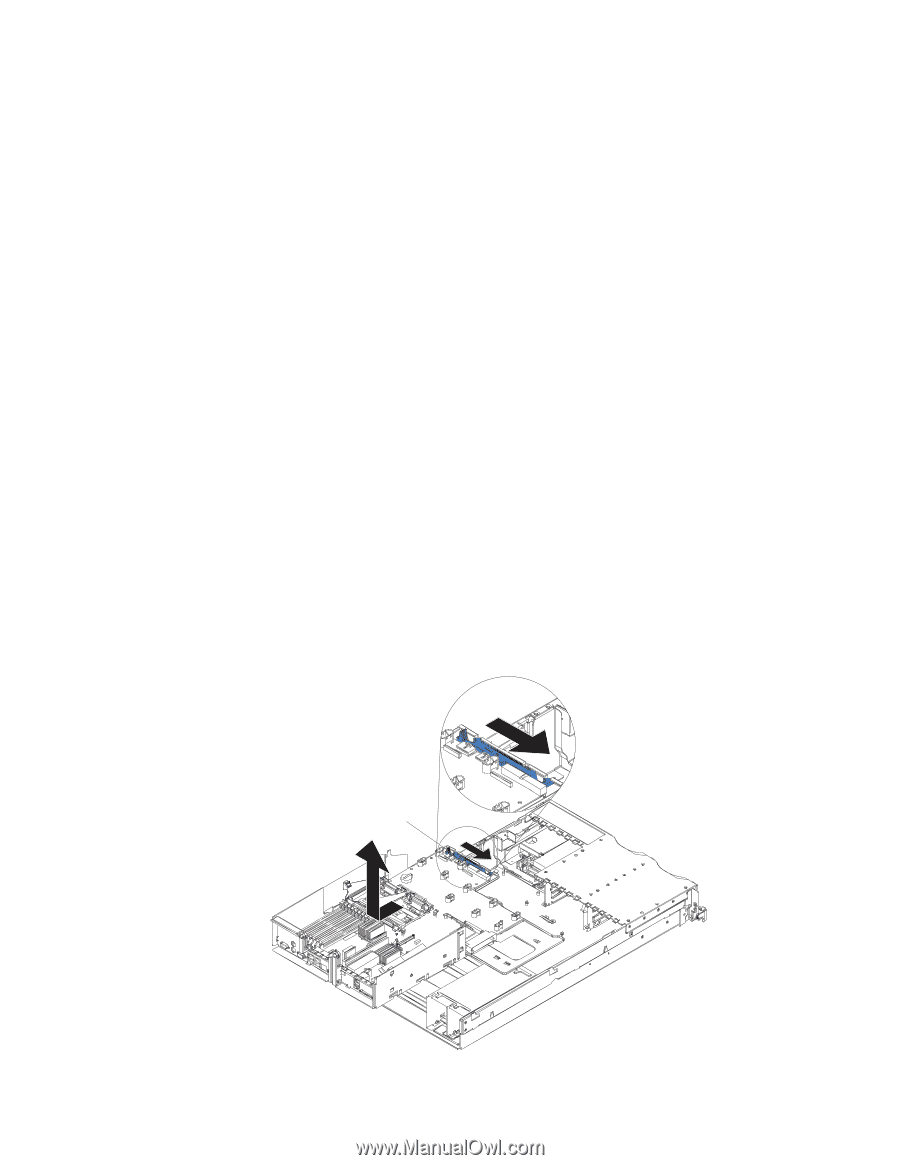
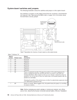
Removing the system board and shuttle This section contains instructions for removing and replacing the system board and shuttle. Note: v Read "Installation guidelines" on page 23. v Read the safety notices at Appendix B, "Safety information," on page 117. v Read "Handling static-sensitive devices" on page 25. Complete the following steps to remove the system board and shuttle: 1. Turn off the server and any attached devices. Note: When replacing the system board, you must either update the server with the latest firmware or restore the pre-existing firmware that the customer provides on a diskette or CD image. 2. Disconnect external cables and option cables from the back of the server. 3. Remove the cover (see "Removing the cover" on page 28). 4. Remove the air baffle (see "Removing the air baffle" on page 29. 5. Remove the fan bracket (see "Fan bracket" on page 60). 6. Disconnect and remove the PCI low-profile-card assembly and PCI riser-card assembly (see "Working with adapters" on page 30). 7. Disconnect all cables from the system board. 8. Remove all microprocessors and VRMs, and set them aside on a static-protected surface for reinstallation (see "Installing a microprocessor" on page 42). 9. Remove the memory modules, and set them aside on a static-protected surface for reinstallation (see "Installing memory modules" on page 39). 10. Remove the power cage assembly (see "Power cage assembly" on page 61). 11. Release the shuttle locking latch, and remove the shuttle from the server. Shuttle locking latch 70 xSeries 346 Types 8840 and 1880: Hardware Maintenance Manual and Troubleshooting Guide
-
 1
1 -
2
-
3
-
4
-
5
-
6
-
7
-
8
-
9
-
10
-
11
-
12
-
13
-
14
-
15
-
16
-
17
-
18
-
19
-
20
-
21
-
22
-
23
-
24
-
25
-
26
-
27
-
28
-
29
-
30
-
31
-
32
-
33
-
34
-
35
-
36
-
37
-
38
-
39
-
40
-
41
-
42
-
43
-
44
-
45
-
46
-
47
-
48
-
49
-
50
-
51
-
52
-
53
-
54
-
55
-
56
-
57
-
58
-
59
-
60
-
61
-
62
-
63
-
64
-
65
-
66
-
67
-
68
-
69
-
70
-
71
-
72
-
73
-
74
-
 75
75 -
 76
76 -
 77
77 -
 78
78 -
 79
79 -
 80
80 -
 81
81 -
 82
82 -
 83
83 -
 84
84 -
 85
85 -
86
-
87
-
88
-
89
-
90
-
91
-
92
-
93
-
94
-
95
-
96
-
97
-
98
-
99
-
100
-
101
-
102
-
103
-
104
-
105
-
106
-
107
-
108
-
109
-
110
-
111
-
112
-
113
-
114
-
115
-
116
-
117
-
118
-
119
-
120
-
121
-
122
-
123
-
124
-
125
-
126
-
127
-
128
-
129
-
130
-
131
-
132
-
133
-
134
-
135
-
136
-
137
-
138
-
139
-
140
-
141
-
142
-
143
-
144
-
145
-
146
-
147
-
148
-
149
-
150
-
151
-
152
-
153
-
154
-
155
-
156
-
157
-
158
-
159
-
160
-
161
-
162
-
163
-
164
-
165
-
166
-
167
-
168
-
169
-
170
-
171
-
172
-
173
-
174
-
175
-
176
 |
 |