IBM 8840 Hardware Maintenance Manual - Page 69
Field, replaceable, units
 |
UPC - 000435863799
View all IBM 8840 manuals
Add to My Manuals
Save this manual to your list of manuals |
Page 69 highlights
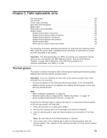
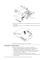
Chapter 5. Field replaceable units Thermal grease 59 Fan bracket 60 Power cage assembly 61 Hard disk drive backplane 62 Media cage 63 Removing a microprocessor 64 System board 66 System-board option connectors 66 System-board internal cable connectors 67 System-board external connectors 67 System-board switches and jumpers 68 System-board LEDs 69 Removing the system board and shuttle 70 The following information describes procedures for removing and installing certain FRU inside the server. Only a qualified service technician is authorized to access the FRU described in this section. Important: The field-replaceable unit (FRU) procedures are intended for trained servicers who are familiar with IBM xSeries products. See the parts listing in "System" on page 108 to determine if the FRU being replaced is a customer-replaceable unit (CRU) or a FRU. Thermal grease This section contains information about removing and replacing the thermal grease between the heat sink and the microprocessor. Important: If you are installing the heat sink on the same processor that it was removed from, be sure that: v The thermal grease on the heat sink and microprocessor is not contaminated. v Addition thermal grease is not added to the existing thermal grease on the heat sink and microprocessor. Note: v Read "Installation guidelines" on page 23. v Read the safety notices at Appendix B, "Safety information," on page 117. v Read "Handling static-sensitive devices" on page 25. Complete the following steps to replace damaged or contaminated thermal grease on the microprocessor and heat sink: 1. Place the heat sink on a clean work surface. 2. Remove the cleaning pad from its package and unfold it completely. 3. Use the cleaning pad to wipe the thermal grease from the bottom of the heat sink. Note: Be sure that all of the thermal grease is removed. 4. Use a clean area of the cleaning pad to wipe the thermal grease from the microprocessor; then, dispose of the cleaning pad after all of the thermal grease is removed. © Copyright IBM Corp. 2005 59
-
 1
1 -
2
-
3
-
4
-
5
-
6
-
7
-
8
-
9
-
10
-
11
-
12
-
13
-
14
-
15
-
16
-
17
-
18
-
19
-
20
-
21
-
22
-
23
-
24
-
25
-
26
-
27
-
28
-
29
-
30
-
31
-
32
-
33
-
34
-
35
-
36
-
37
-
38
-
39
-
40
-
41
-
42
-
43
-
44
-
45
-
46
-
47
-
48
-
49
-
50
-
51
-
52
-
53
-
54
-
55
-
56
-
57
-
58
-
59
-
60
-
61
-
62
-
63
-
 64
64 -
 65
65 -
 66
66 -
 67
67 -
 68
68 -
 69
69 -
 70
70 -
 71
71 -
 72
72 -
 73
73 -
 74
74 -
75
-
76
-
77
-
78
-
79
-
80
-
81
-
82
-
83
-
84
-
85
-
86
-
87
-
88
-
89
-
90
-
91
-
92
-
93
-
94
-
95
-
96
-
97
-
98
-
99
-
100
-
101
-
102
-
103
-
104
-
105
-
106
-
107
-
108
-
109
-
110
-
111
-
112
-
113
-
114
-
115
-
116
-
117
-
118
-
119
-
120
-
121
-
122
-
123
-
124
-
125
-
126
-
127
-
128
-
129
-
130
-
131
-
132
-
133
-
134
-
135
-
136
-
137
-
138
-
139
-
140
-
141
-
142
-
143
-
144
-
145
-
146
-
147
-
148
-
149
-
150
-
151
-
152
-
153
-
154
-
155
-
156
-
157
-
158
-
159
-
160
-
161
-
162
-
163
-
164
-
165
-
166
-
167
-
168
-
169
-
170
-
171
-
172
-
173
-
174
-
175
-
176
 |
 |