IBM 8840 Hardware Maintenance Manual - Page 62
Connecting, cables
 |
UPC - 000435863799
View all IBM 8840 manuals
Add to My Manuals
Save this manual to your list of manuals |
Page 62 highlights
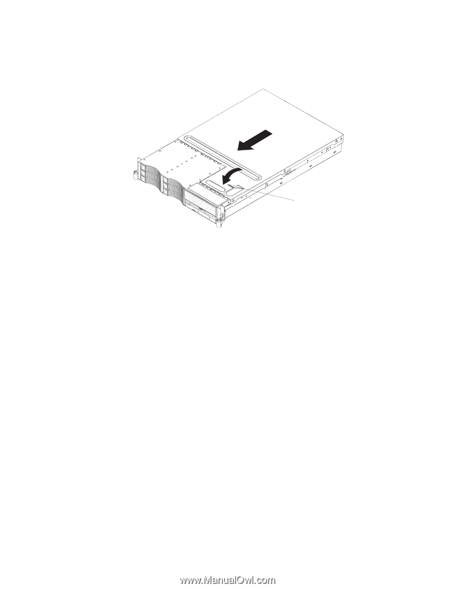
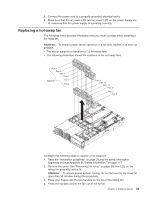
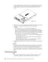
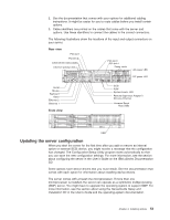
1. If you removed the server cover, place the cover-release latch in the open (up) position. Insert the bottom tabs of the top cover into the matching slots in the server chassis. Press down on the cover-release latch to lock the cover in place. Cover-release latch 2. Install the server in a rack. See the Rack Installation Instructions that come with the server for complete rack installation and removal instructions. Attention: v Install the server only in a rack cabinet with perforated doors. v Do not leave open spaces above or below an installed server in the rack cabinet. To help prevent damage to server components, always install a blank filler panel to cover the open space and to help ensure proper air circulation. See the documentation that comes with the rack cabinet for more information. v Install the server in a rack that meets the following requirements: - Minimum depth of 70 mm (2.76 in.) between the front mounting flange and the inside of the front door - Minimum depth of 157 mm (6.18 in.) between the rear mounting flange and the inside of the rear door - Minimum depth of 718 mm (28.27 in.) and maximum depth of 762 mm (30.00 in.) between the front and rear mounting flanges 3. To attach peripheral devices and connect the power cords, see "Connecting the cables." Attention: v For proper cooling and airflow, replace the server cover before or shortly after turning on the server. Operating the server for extended periods of time (over 30 minutes) with the server cover removed might damage server components. v To ensure proper server operation, do not remove the air baffle from the server except when installing or removing the components that are located under the air baffle. Connecting the cables Notes: 1. You must turn off the server (see "Turning off the server" on page 7) before connecting any cables to or disconnecting any cables from the server. 52 xSeries 346 Types 8840 and 1880: Hardware Maintenance Manual and Troubleshooting Guide
-
 1
1 -
2
-
3
-
4
-
5
-
6
-
7
-
8
-
9
-
10
-
11
-
12
-
13
-
14
-
15
-
16
-
17
-
18
-
19
-
20
-
21
-
22
-
23
-
24
-
25
-
26
-
27
-
28
-
29
-
30
-
31
-
32
-
33
-
34
-
35
-
36
-
37
-
38
-
39
-
40
-
41
-
42
-
43
-
44
-
45
-
46
-
47
-
48
-
49
-
50
-
51
-
52
-
53
-
54
-
55
-
56
-
 57
57 -
 58
58 -
 59
59 -
 60
60 -
 61
61 -
 62
62 -
 63
63 -
 64
64 -
 65
65 -
 66
66 -
 67
67 -
68
-
69
-
70
-
71
-
72
-
73
-
74
-
75
-
76
-
77
-
78
-
79
-
80
-
81
-
82
-
83
-
84
-
85
-
86
-
87
-
88
-
89
-
90
-
91
-
92
-
93
-
94
-
95
-
96
-
97
-
98
-
99
-
100
-
101
-
102
-
103
-
104
-
105
-
106
-
107
-
108
-
109
-
110
-
111
-
112
-
113
-
114
-
115
-
116
-
117
-
118
-
119
-
120
-
121
-
122
-
123
-
124
-
125
-
126
-
127
-
128
-
129
-
130
-
131
-
132
-
133
-
134
-
135
-
136
-
137
-
138
-
139
-
140
-
141
-
142
-
143
-
144
-
145
-
146
-
147
-
148
-
149
-
150
-
151
-
152
-
153
-
154
-
155
-
156
-
157
-
158
-
159
-
160
-
161
-
162
-
163
-
164
-
165
-
166
-
167
-
168
-
169
-
170
-
171
-
172
-
173
-
174
-
175
-
176
 |
 |