IBM 8840 Hardware Maintenance Manual - Page 109
Power-supply, errors, Service, processor, error, codes
 |
UPC - 000435863799
View all IBM 8840 manuals
Add to My Manuals
Save this manual to your list of manuals |
Page 109 highlights
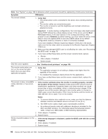
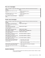
Power-supply LED errors Use the information in this section to solve power-supply problems. Note: The minimum configuration required for the dc good light to be lit is: v Power supply v Power cage assembly. v System board (set switch 1 of SW2 to bypass the power switch; see "System-board switches and jumpers" on page 68). Note: See "System" on page 108 to determine which components a field service technician should replace. AC good LED DC good LED Description FRU/action Off Off No power to system or ac problem. 1. Check ac power to the system. 2. Power supply. On Off Standby mode or dc problem. 1. Move switch 1 of SW 2 to bypass power control. If the dc good LED is lit, press Ctrl+Alt+Delete. Watch the screen for any POST errors. Check the system-error log and BMC log for any listed problems. If the system starts with no errors: a. Power switch assembly b. System board 2. Remove the adapters, and disconnect the cables and power connectors to all internal and external devices. Turn on the system. If the dc good LED is lit, replace the adapters and devices one at a time until you isolate the problem. 3. Power supply. 4. Power cage assembly. 5. System board. On On Power is working properly. N/A Service processor error codes When viewed in the system-error log, the Remote Supervisor Adapter II SlimLine messages will appear as text descriptions. To determine a possible error condition for the Remote Supervisor Adapter II SlimLine, see the system-error log (see "Viewing error logs from diagnostic programs" on page 13). SCSI error codes Note: If a ServeRAID-7k controller is installed and later removed, you must re-enable the on-board SCSI controller in using the Configuration/Setup Utility program (see Chapter 2, "Configuring the server," on page 9). Chapter 6. Symptom-to-FRU index 99
-
 1
1 -
2
-
3
-
4
-
5
-
6
-
7
-
8
-
9
-
10
-
11
-
12
-
13
-
14
-
15
-
16
-
17
-
18
-
19
-
20
-
21
-
22
-
23
-
24
-
25
-
26
-
27
-
28
-
29
-
30
-
31
-
32
-
33
-
34
-
35
-
36
-
37
-
38
-
39
-
40
-
41
-
42
-
43
-
44
-
45
-
46
-
47
-
48
-
49
-
50
-
51
-
52
-
53
-
54
-
55
-
56
-
57
-
58
-
59
-
60
-
61
-
62
-
63
-
64
-
65
-
66
-
67
-
68
-
69
-
70
-
71
-
72
-
73
-
74
-
75
-
76
-
77
-
78
-
79
-
80
-
81
-
82
-
83
-
84
-
85
-
86
-
87
-
88
-
89
-
90
-
91
-
92
-
93
-
94
-
95
-
96
-
97
-
98
-
99
-
100
-
101
-
102
-
103
-
 104
104 -
 105
105 -
 106
106 -
 107
107 -
 108
108 -
 109
109 -
 110
110 -
 111
111 -
 112
112 -
 113
113 -
 114
114 -
115
-
116
-
117
-
118
-
119
-
120
-
121
-
122
-
123
-
124
-
125
-
126
-
127
-
128
-
129
-
130
-
131
-
132
-
133
-
134
-
135
-
136
-
137
-
138
-
139
-
140
-
141
-
142
-
143
-
144
-
145
-
146
-
147
-
148
-
149
-
150
-
151
-
152
-
153
-
154
-
155
-
156
-
157
-
158
-
159
-
160
-
161
-
162
-
163
-
164
-
165
-
166
-
167
-
168
-
169
-
170
-
171
-
172
-
173
-
174
-
175
-
176
 |
 |