IBM 8840 Hardware Maintenance Manual - Page 54
Heat sink, Microprocessor, baffle, Microprocessor, release lever
 |
UPC - 000435863799
View all IBM 8840 manuals
Add to My Manuals
Save this manual to your list of manuals |
Page 54 highlights
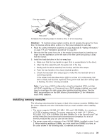
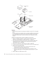
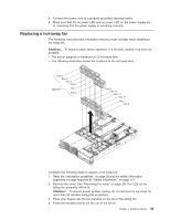
VRM Microprocessor baffle Heat sink Microprocessor Microprocessorrelease lever Attention: v A startup (boot) processor must always be installed in socket J22 on the system board. v To ensure proper server operation when you install an additional microprocessor, use microprocessors that have the same cache size and type, and the same clock speed. Microprocessor internal and external clock frequencies must be identical. Complete the following steps to install an additional microprocessor: 1. Read the "Installation guidelines" on page 23.and the safety information beginning on page Appendix B, "Safety information," on page 117. 2. Turn off the server and disconnect all power cords and external cables (see "Turning off the server" on page 7); then, remove the server cover (see "Removing the cover" on page 28). 3. Remove the air baffle (see "Removing the air baffle" on page 29). 4. Locate the second microprocessor socket (connector J23) on the system board. 5. Remove the microprocessor baffle. a. Press the heat-sink release lever to unhook it from the tab on the microprocessor socket; then, pull the lever up. b. Slide the microprocessor baffle while lifting the rear flange out of the heat-sink socket; then, lift it off the heat-sink socket and store it in a safe place. 6. Install a VRM in the VRM connector (J72). 44 xSeries 346 Types 8840 and 1880: Hardware Maintenance Manual and Troubleshooting Guide
-
 1
1 -
2
-
3
-
4
-
5
-
6
-
7
-
8
-
9
-
10
-
11
-
12
-
13
-
14
-
15
-
16
-
17
-
18
-
19
-
20
-
21
-
22
-
23
-
24
-
25
-
26
-
27
-
28
-
29
-
30
-
31
-
32
-
33
-
34
-
35
-
36
-
37
-
38
-
39
-
40
-
41
-
42
-
43
-
44
-
45
-
46
-
47
-
48
-
 49
49 -
 50
50 -
 51
51 -
 52
52 -
 53
53 -
 54
54 -
 55
55 -
 56
56 -
 57
57 -
 58
58 -
 59
59 -
60
-
61
-
62
-
63
-
64
-
65
-
66
-
67
-
68
-
69
-
70
-
71
-
72
-
73
-
74
-
75
-
76
-
77
-
78
-
79
-
80
-
81
-
82
-
83
-
84
-
85
-
86
-
87
-
88
-
89
-
90
-
91
-
92
-
93
-
94
-
95
-
96
-
97
-
98
-
99
-
100
-
101
-
102
-
103
-
104
-
105
-
106
-
107
-
108
-
109
-
110
-
111
-
112
-
113
-
114
-
115
-
116
-
117
-
118
-
119
-
120
-
121
-
122
-
123
-
124
-
125
-
126
-
127
-
128
-
129
-
130
-
131
-
132
-
133
-
134
-
135
-
136
-
137
-
138
-
139
-
140
-
141
-
142
-
143
-
144
-
145
-
146
-
147
-
148
-
149
-
150
-
151
-
152
-
153
-
154
-
155
-
156
-
157
-
158
-
159
-
160
-
161
-
162
-
163
-
164
-
165
-
166
-
167
-
168
-
169
-
170
-
171
-
172
-
173
-
174
-
175
-
176
 |
 |
