IBM 8840 Hardware Maintenance Manual - Page 65
Input/output, connectors, Auxiliary-device, pointing, device, connector
 |
UPC - 000435863799
View all IBM 8840 manuals
Add to My Manuals
Save this manual to your list of manuals |
Page 65 highlights
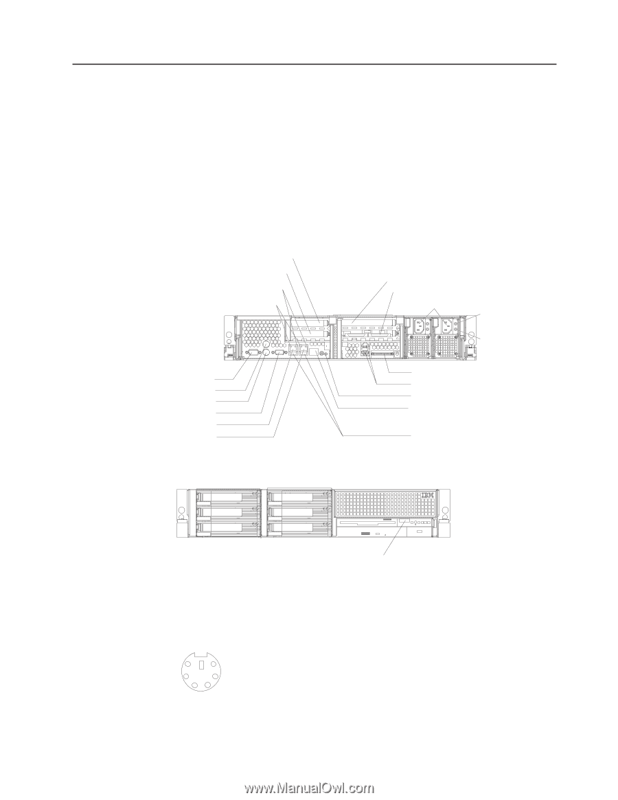
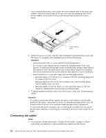
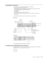
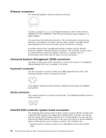
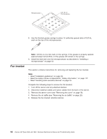
Input/output connectors Your server has the following input/output (I/O) connectors: v One auxiliary-device (pointing device) v Three Ethernet (one for remote server management using network, RJ-45) v Two Advanced Systems Management (ASM) v One keyboard v One serial v One Ultra320 SCSI controller (LVD) SCSI v Three Universal Serial Bus (USB) (one on the front and two on the rear) v One video The following illustrations show the locations of these connectors. Rear view PCI slot 1 PCI slot 2 Ethernet link status LEDs Ethernet activity LEDs PCI slot 3 PCI slot 4 Power cords AC power LED TX/RX LINK TX/RX LINK DC power LED Serial Mouse Keyboard Video Ethernet 2 Ethernet 1 Front view SCSI ASM System-locator LED Remote Supervisor Adapter II SlimLine Ethernet Universal Serial Bus (USB) USB The following sections describe these connectors. Auxiliary-device (pointing device) connector Use this connector to connect a mouse or other pointing device. The following illustration shows an auxiliary-device connector. 6 4 2 5 3 1 Chapter 4. Installing options 55
-
 1
1 -
2
-
3
-
4
-
5
-
6
-
7
-
8
-
9
-
10
-
11
-
12
-
13
-
14
-
15
-
16
-
17
-
18
-
19
-
20
-
21
-
22
-
23
-
24
-
25
-
26
-
27
-
28
-
29
-
30
-
31
-
32
-
33
-
34
-
35
-
36
-
37
-
38
-
39
-
40
-
41
-
42
-
43
-
44
-
45
-
46
-
47
-
48
-
49
-
50
-
51
-
52
-
53
-
54
-
55
-
56
-
57
-
58
-
59
-
 60
60 -
 61
61 -
 62
62 -
 63
63 -
 64
64 -
 65
65 -
 66
66 -
 67
67 -
 68
68 -
 69
69 -
 70
70 -
71
-
72
-
73
-
74
-
75
-
76
-
77
-
78
-
79
-
80
-
81
-
82
-
83
-
84
-
85
-
86
-
87
-
88
-
89
-
90
-
91
-
92
-
93
-
94
-
95
-
96
-
97
-
98
-
99
-
100
-
101
-
102
-
103
-
104
-
105
-
106
-
107
-
108
-
109
-
110
-
111
-
112
-
113
-
114
-
115
-
116
-
117
-
118
-
119
-
120
-
121
-
122
-
123
-
124
-
125
-
126
-
127
-
128
-
129
-
130
-
131
-
132
-
133
-
134
-
135
-
136
-
137
-
138
-
139
-
140
-
141
-
142
-
143
-
144
-
145
-
146
-
147
-
148
-
149
-
150
-
151
-
152
-
153
-
154
-
155
-
156
-
157
-
158
-
159
-
160
-
161
-
162
-
163
-
164
-
165
-
166
-
167
-
168
-
169
-
170
-
171
-
172
-
173
-
174
-
175
-
176
 |
 |