IBM 8840 Hardware Maintenance Manual - Page 71
Power, assembly
 |
UPC - 000435863799
View all IBM 8840 manuals
Add to My Manuals
Save this manual to your list of manuals |
Page 71 highlights
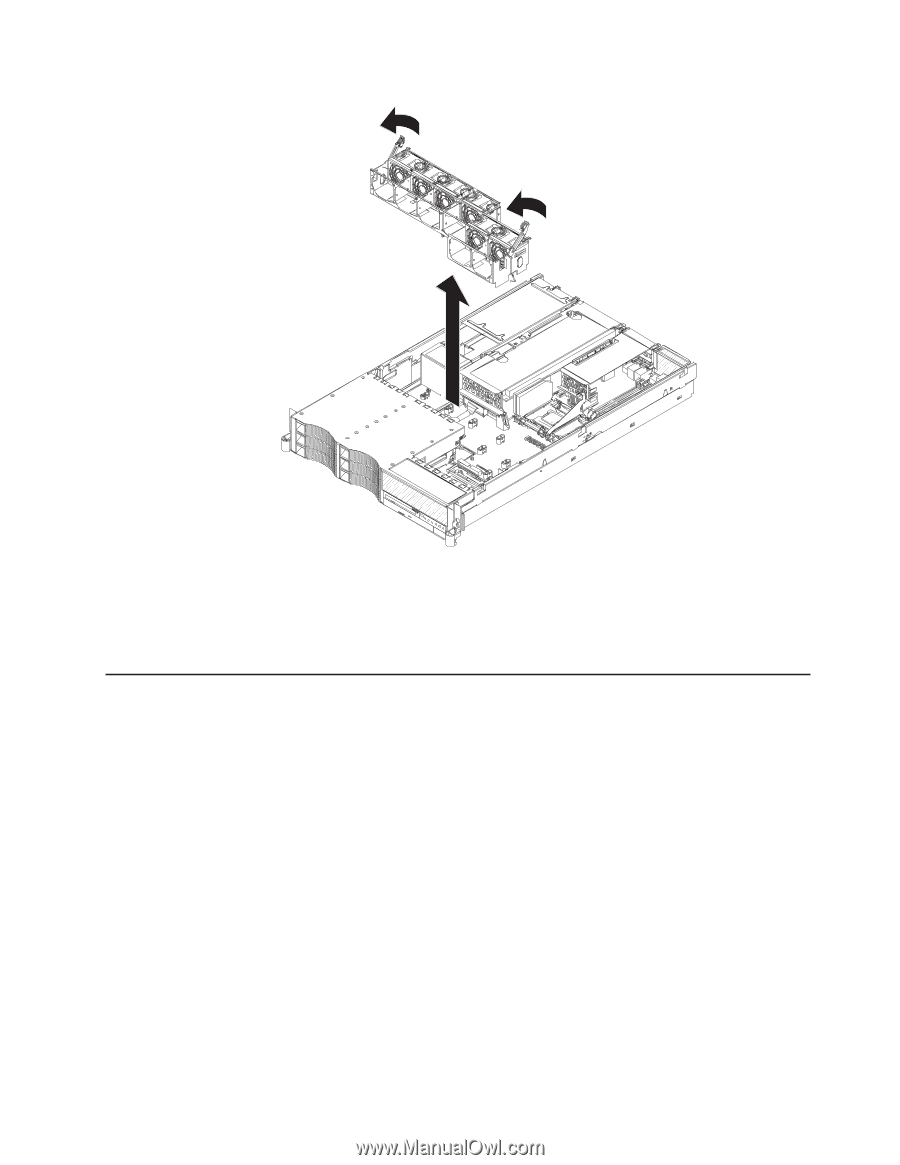
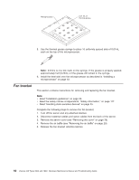
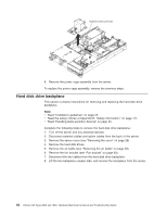
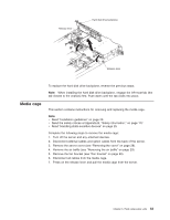
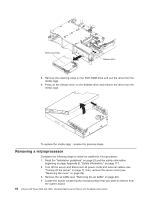
6. Remove the fan bracket from the server. 7. Remove the fans (see "Replacing a hot-swap fan" on page 49). To replace the fan bracket, reverse the previous steps. Power cage assembly This section contains instructions for removing and replacing the power cage assembly. Note: v Read "Installation guidelines" on page 23. v Read the safety notices at Appendix B, "Safety information," on page 117. v Read "Handling static-sensitive devices" on page 25. Complete the following steps to remove the power cage assembly: 1. Turn off the server and any attached devices. 2. Disconnect external cables and option cables from the back of the server. 3. Remove the server cover (see "Removing the cover" on page 28). 4. Remove the air baffle (see "Removing the air baffle" on page 29). 5. Remove the PCI riser-card assembly (see "Working with adapters" on page 30). 6. Disconnect the power supplies from the power cage assembly. 7. Looking from the front of the server, slide the power cage assembly toward the left side of the server to disconnect the cage assembly from the system board connector. Chapter 5. Field replaceable units 61
-
 1
1 -
2
-
3
-
4
-
5
-
6
-
7
-
8
-
9
-
10
-
11
-
12
-
13
-
14
-
15
-
16
-
17
-
18
-
19
-
20
-
21
-
22
-
23
-
24
-
25
-
26
-
27
-
28
-
29
-
30
-
31
-
32
-
33
-
34
-
35
-
36
-
37
-
38
-
39
-
40
-
41
-
42
-
43
-
44
-
45
-
46
-
47
-
48
-
49
-
50
-
51
-
52
-
53
-
54
-
55
-
56
-
57
-
58
-
59
-
60
-
61
-
62
-
63
-
64
-
65
-
 66
66 -
 67
67 -
 68
68 -
 69
69 -
 70
70 -
 71
71 -
 72
72 -
 73
73 -
 74
74 -
 75
75 -
 76
76 -
77
-
78
-
79
-
80
-
81
-
82
-
83
-
84
-
85
-
86
-
87
-
88
-
89
-
90
-
91
-
92
-
93
-
94
-
95
-
96
-
97
-
98
-
99
-
100
-
101
-
102
-
103
-
104
-
105
-
106
-
107
-
108
-
109
-
110
-
111
-
112
-
113
-
114
-
115
-
116
-
117
-
118
-
119
-
120
-
121
-
122
-
123
-
124
-
125
-
126
-
127
-
128
-
129
-
130
-
131
-
132
-
133
-
134
-
135
-
136
-
137
-
138
-
139
-
140
-
141
-
142
-
143
-
144
-
145
-
146
-
147
-
148
-
149
-
150
-
151
-
152
-
153
-
154
-
155
-
156
-
157
-
158
-
159
-
160
-
161
-
162
-
163
-
164
-
165
-
166
-
167
-
168
-
169
-
170
-
171
-
172
-
173
-
174
-
175
-
176
 |
 |