IBM 8840 Hardware Maintenance Manual - Page 63
Updating, server, configuration
 |
UPC - 000435863799
View all IBM 8840 manuals
Add to My Manuals
Save this manual to your list of manuals |
Page 63 highlights
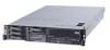
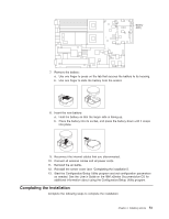
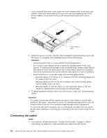
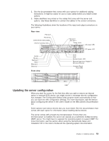
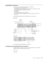
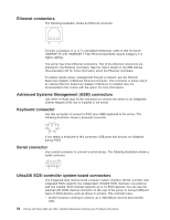
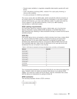
2. See the documentation that comes with your options for additional cabling instructions. It might be easier for you to route cables before you install certain options. 3. Cable identifiers are printed on the cables that come with the server and options. Use these identifiers to connect the cables to the correct connectors. The following illustrations show the locations of the input and output connectors on your server. Rear view PCI slot 1 PCI slot 2 Ethernet link status LEDs Ethernet activity LEDs PCI slot 3 PCI slot 4 Power cords AC power LED TX/RX LINK TX/RX LINK DC power LED Serial Mouse Keyboard Video Ethernet 2 Ethernet 1 Front view SCSI ASM System-locator LED Remote Supervisor Adapter II SlimLine Ethernet Universal Serial Bus (USB) USB Updating the server configuration When you start the server for the first time after you add or remove an internal option or external SCSI device, you might receive a message that the configuration has changed. The Configuration/Setup Utility program starts automatically so that you can save the new configuration settings. For more information, see the section about configuring the server in the User's Guide on the IBM xSeries Documentation CD. Some options have device drivers that you must install. See the documentation that comes with each option for information about installing device drivers. The server comes with at least one microprocessor. If more than one microprocessor is installed, the server can operate as a symmetric multiprocessing (SMP) server. You might have to upgrade the operating system to support SMP. For more information, see the section about using the ServerGuide Setup and Installation CD in the User's Guide and the operating-system documentation. Chapter 4. Installing options 53
-
 1
1 -
2
-
3
-
4
-
5
-
6
-
7
-
8
-
9
-
10
-
11
-
12
-
13
-
14
-
15
-
16
-
17
-
18
-
19
-
20
-
21
-
22
-
23
-
24
-
25
-
26
-
27
-
28
-
29
-
30
-
31
-
32
-
33
-
34
-
35
-
36
-
37
-
38
-
39
-
40
-
41
-
42
-
43
-
44
-
45
-
46
-
47
-
48
-
49
-
50
-
51
-
52
-
53
-
54
-
55
-
56
-
57
-
 58
58 -
 59
59 -
 60
60 -
 61
61 -
 62
62 -
 63
63 -
 64
64 -
 65
65 -
 66
66 -
 67
67 -
 68
68 -
69
-
70
-
71
-
72
-
73
-
74
-
75
-
76
-
77
-
78
-
79
-
80
-
81
-
82
-
83
-
84
-
85
-
86
-
87
-
88
-
89
-
90
-
91
-
92
-
93
-
94
-
95
-
96
-
97
-
98
-
99
-
100
-
101
-
102
-
103
-
104
-
105
-
106
-
107
-
108
-
109
-
110
-
111
-
112
-
113
-
114
-
115
-
116
-
117
-
118
-
119
-
120
-
121
-
122
-
123
-
124
-
125
-
126
-
127
-
128
-
129
-
130
-
131
-
132
-
133
-
134
-
135
-
136
-
137
-
138
-
139
-
140
-
141
-
142
-
143
-
144
-
145
-
146
-
147
-
148
-
149
-
150
-
151
-
152
-
153
-
154
-
155
-
156
-
157
-
158
-
159
-
160
-
161
-
162
-
163
-
164
-
165
-
166
-
167
-
168
-
169
-
170
-
171
-
172
-
173
-
174
-
175
-
176
 |
 |
