IBM 8840 Hardware Maintenance Manual - Page 77
System-board, internal, cable, connectors, external
 |
UPC - 000435863799
View all IBM 8840 manuals
Add to My Manuals
Save this manual to your list of manuals |
Page 77 highlights
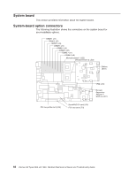
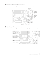
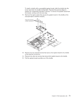
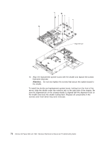
System-board internal cable connectors The following illustration shows the internal connectors on the system board. Internal SCSI (J25) Operator panel (J37) Fan 8 Fan 2 USB operator panel (J75) Media power (J63) Fan 1 Diskette signal (J39) IDE (J67) Fan 6 Fan 7 Fan 12 Fan 5 Fan 11 Fan 4 Power Fan 10 backplane (J41) System-board external connectors The following illustration shows the external input/output connectors on the system board. Serial (J9) Keyboard/Mouse (J10) Video (J11) Ethernet 2/USB (J14) Ethernet 1/USB (J12) Remote Supervisor Adapter II SlimLine Ethernet (J15) ASM (J16) External SCSI (J17) Chapter 5. Field replaceable units 67
-
 1
1 -
2
-
3
-
4
-
5
-
6
-
7
-
8
-
9
-
10
-
11
-
12
-
13
-
14
-
15
-
16
-
17
-
18
-
19
-
20
-
21
-
22
-
23
-
24
-
25
-
26
-
27
-
28
-
29
-
30
-
31
-
32
-
33
-
34
-
35
-
36
-
37
-
38
-
39
-
40
-
41
-
42
-
43
-
44
-
45
-
46
-
47
-
48
-
49
-
50
-
51
-
52
-
53
-
54
-
55
-
56
-
57
-
58
-
59
-
60
-
61
-
62
-
63
-
64
-
65
-
66
-
67
-
68
-
69
-
70
-
71
-
 72
72 -
 73
73 -
 74
74 -
 75
75 -
 76
76 -
 77
77 -
 78
78 -
 79
79 -
 80
80 -
 81
81 -
 82
82 -
83
-
84
-
85
-
86
-
87
-
88
-
89
-
90
-
91
-
92
-
93
-
94
-
95
-
96
-
97
-
98
-
99
-
100
-
101
-
102
-
103
-
104
-
105
-
106
-
107
-
108
-
109
-
110
-
111
-
112
-
113
-
114
-
115
-
116
-
117
-
118
-
119
-
120
-
121
-
122
-
123
-
124
-
125
-
126
-
127
-
128
-
129
-
130
-
131
-
132
-
133
-
134
-
135
-
136
-
137
-
138
-
139
-
140
-
141
-
142
-
143
-
144
-
145
-
146
-
147
-
148
-
149
-
150
-
151
-
152
-
153
-
154
-
155
-
156
-
157
-
158
-
159
-
160
-
161
-
162
-
163
-
164
-
165
-
166
-
167
-
168
-
169
-
170
-
171
-
172
-
173
-
174
-
175
-
176
 |
 |

System-board
internal
cable
connectors
The
following
illustration
shows
the
internal
connectors
on
the
system
board.
Fan 2
Fan 1
Fan 6
Fan 5
Fan 4
Fan 10
Fan 11
Fan 12
Fan 7
Fan 8
Operator
panel (J37)
USB operator
panel (J75)
Media power
(J63)
Diskette
signal (J39)
IDE (J67)
Internal
SCSI (J25)
Power
backplane (J41)
System-board
external
connectors
The
following
illustration
shows
the
external
input/output
connectors
on
the
system
board.
Serial (J9)
Keyboard/Mouse (J10)
Video (J11)
Ethernet 1/USB (J12)
Ethernet 2/USB (J14)
Remote Supervisor
Adapter II
Ethernet (J15)
SlimLine
ASM (J16)
External SCSI (J17)
Chapter
5.
Field
replaceable
units
67