IBM 8840 Hardware Maintenance Manual - Page 27
Power, supply, Light, diagnostics - specs
 |
UPC - 000435863799
View all IBM 8840 manuals
Add to My Manuals
Save this manual to your list of manuals |
Page 27 highlights
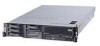
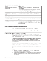
Configuration/Setup Utility program so that you can change or delete the power-on password. You do not have to move the switch back to the default position after the password is overridden. Changing the position of this switch does not affect the administrator password. Power supply LEDs The ac and dc power LEDs on the power supply provide status information about the power supply. The following illustration shows the location of the ac and dc power LEDs. AC power LED (green) DC power LED (green) For more information about power supply LEDs, see "Power-supply LED errors" on page 99. Light path diagnostics Use light path diagnostics to diagnose system errors. The light path diagnostics panel is inside the light path diagnostics drawer, on the right front of the server. To access the light path diagnostics panel, slide the latch to the left on the front of the light path diagnostics drawer. The following illustration shows the controls and LEDs on the light path diagnostics panel. Light Path Diagnostics REMIND OVER SPEC PS1 PS2 CPU VRM CNFG MEM NMI S ERR SP DASD RAID FAN TEMP BRD PCI A PCI B PCI C To acknowledge a system error but not take immediate action, press the remind button and place light path diagnostics in remind mode. When the server is in remind mode, the system-error LED on the front of the server flashes. If a new failure occurs, the system-error LED is lit again. Chapter 3. Diagnostics 17
-
 1
1 -
2
-
3
-
4
-
5
-
6
-
7
-
8
-
9
-
10
-
11
-
12
-
13
-
14
-
15
-
16
-
17
-
18
-
19
-
20
-
21
-
 22
22 -
 23
23 -
 24
24 -
 25
25 -
 26
26 -
 27
27 -
 28
28 -
 29
29 -
 30
30 -
 31
31 -
 32
32 -
33
-
34
-
35
-
36
-
37
-
38
-
39
-
40
-
41
-
42
-
43
-
44
-
45
-
46
-
47
-
48
-
49
-
50
-
51
-
52
-
53
-
54
-
55
-
56
-
57
-
58
-
59
-
60
-
61
-
62
-
63
-
64
-
65
-
66
-
67
-
68
-
69
-
70
-
71
-
72
-
73
-
74
-
75
-
76
-
77
-
78
-
79
-
80
-
81
-
82
-
83
-
84
-
85
-
86
-
87
-
88
-
89
-
90
-
91
-
92
-
93
-
94
-
95
-
96
-
97
-
98
-
99
-
100
-
101
-
102
-
103
-
104
-
105
-
106
-
107
-
108
-
109
-
110
-
111
-
112
-
113
-
114
-
115
-
116
-
117
-
118
-
119
-
120
-
121
-
122
-
123
-
124
-
125
-
126
-
127
-
128
-
129
-
130
-
131
-
132
-
133
-
134
-
135
-
136
-
137
-
138
-
139
-
140
-
141
-
142
-
143
-
144
-
145
-
146
-
147
-
148
-
149
-
150
-
151
-
152
-
153
-
154
-
155
-
156
-
157
-
158
-
159
-
160
-
161
-
162
-
163
-
164
-
165
-
166
-
167
-
168
-
169
-
170
-
171
-
172
-
173
-
174
-
175
-
176
 |
 |