IBM 8840 Hardware Maintenance Manual - Page 67
cabling, requirements, connector
 |
UPC - 000435863799
View all IBM 8840 manuals
Add to My Manuals
Save this manual to your list of manuals |
Page 67 highlights
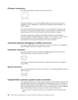
v Domain-name validation to negotiate compatible data-transfer speeds with each device v Cyclic redundancy checking (CRC), instead of the usual parity checking, to improve data reliability v An active terminator for SCSI bus termination The server comes with one SCSI cable, which connects the internal connector on the system board to the standard hot-swap-drive backplane. If you plan to attach external SCSI devices, you must order additional cables. To select and order the correct cables for use with external devices, contact your IBM marketing representative or authorized reseller. SCSI cabling requirements For information about the maximum length of SCSI cable, go to the American National Standards Institute (ANSI) SCSI standards on the ANSI Web site at http://www.ansi.org/. Adhering to these standards will help to ensure that the server operates properly. SCSI IDs Each SCSI device that is connected to a SCSI controller must have a unique SCSI ID. This ID enables the SCSI controller to identify the device and ensure that different devices on the same SCSI channel do not attempt to transfer data simultaneously. SCSI devices that are connected to different SCSI channels can have duplicate SCSI IDs. Table 6 lists the SCSI IDs for the hard disk drives and backplanes that are connected to one channel. Table 6. SCSI IDs for standard hot-swap hard disk drives, controller, and backplane Device SCSI ID Drive bay 1 0 Drive bay 2 1 Drive bay 3 2 Drive bay 4 3 Drive bay 5 4 Drive bay 6 5 Controller 7 Backplane 8 The hot-swap-drive backplane controls the SCSI IDs for the internal hot-swap drive bays. However, when you attach an external SCSI device to an optional SCSI adapter, you must set a unique ID for the device. See the information that comes with the device for instructions for setting its SCSI ID. SCSI connector The following illustration shows a SCSI connector. 34 1 68 35 Chapter 4. Installing options 57
-
 1
1 -
2
-
3
-
4
-
5
-
6
-
7
-
8
-
9
-
10
-
11
-
12
-
13
-
14
-
15
-
16
-
17
-
18
-
19
-
20
-
21
-
22
-
23
-
24
-
25
-
26
-
27
-
28
-
29
-
30
-
31
-
32
-
33
-
34
-
35
-
36
-
37
-
38
-
39
-
40
-
41
-
42
-
43
-
44
-
45
-
46
-
47
-
48
-
49
-
50
-
51
-
52
-
53
-
54
-
55
-
56
-
57
-
58
-
59
-
60
-
61
-
 62
62 -
 63
63 -
 64
64 -
 65
65 -
 66
66 -
 67
67 -
 68
68 -
 69
69 -
 70
70 -
 71
71 -
 72
72 -
73
-
74
-
75
-
76
-
77
-
78
-
79
-
80
-
81
-
82
-
83
-
84
-
85
-
86
-
87
-
88
-
89
-
90
-
91
-
92
-
93
-
94
-
95
-
96
-
97
-
98
-
99
-
100
-
101
-
102
-
103
-
104
-
105
-
106
-
107
-
108
-
109
-
110
-
111
-
112
-
113
-
114
-
115
-
116
-
117
-
118
-
119
-
120
-
121
-
122
-
123
-
124
-
125
-
126
-
127
-
128
-
129
-
130
-
131
-
132
-
133
-
134
-
135
-
136
-
137
-
138
-
139
-
140
-
141
-
142
-
143
-
144
-
145
-
146
-
147
-
148
-
149
-
150
-
151
-
152
-
153
-
154
-
155
-
156
-
157
-
158
-
159
-
160
-
161
-
162
-
163
-
164
-
165
-
166
-
167
-
168
-
169
-
170
-
171
-
172
-
173
-
174
-
175
-
176
 |
 |