Icom ID-1 Instruction Manual
Icom ID-1 Manual
 |
View all Icom ID-1 manuals
Add to My Manuals
Save this manual to your list of manuals |
Icom ID-1 manual content summary:
- Icom ID-1 | Instruction Manual - Page 1
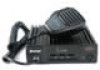
INSTRUCTION MANUAL DIGITAL TRANSCEIVER ID-1 DIGITAL TRANSCEIVER ID-1 MIC TD/RD PWR TX/RX POWER - Icom ID-1 | Instruction Manual - Page 2
with Icom's philosophy of "technology first." Many hours of research and development went into the design of your ID-1. D FEATURES ❍ Current FM, Digital Voice and Data modes available ❍ Standard PC control application via USB terminal connection ❍ Remote controller for current mobile transceiver - Icom ID-1 | Instruction Manual - Page 3
or non resonant antenna may damage the transceiver. R WARNING for data mode operation! The saved file(s) in the shared folder may be modified or deleted, or unknown file(s) may be copied into the shared folder from the connected station when the transmission inhibit is released. Icom Inc. assume no - Icom ID-1 | Instruction Manual - Page 4
ID-1 only. iii If a connection cable is disconnected or has a loose connection during operation, an error may occur. Connect the connectors correctly, and DO NOT touch the connectors during operation. For the operation of PC and peripheral devices, follow the instructions provided in the manuals - Icom ID-1 | Instruction Manual - Page 5
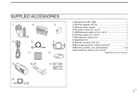
u o !0 y i !1 q Microphone (HM-118N 1 w External speaker (SP-22 1 e Ethernet cable coupler 1 r DC power cable (3 m; 9.8 ft 1 t USB extension cable (1.5 m; 4.9 ft 1 y Ethernet cable (3 m; 9.8 ft 1 u Self-adhesive rubber feet 1 i Application CD 1 o Remote controller (RC-24 1 !0 Mounting - Icom ID-1 | Instruction Manual - Page 6
13-17 Unpacking 13 Selecting a location 13 Antenna connection 13 Power supply connections 15 Microphone and speaker connections 16 Connecting a PC 17 3 DRIVER INSTALLATION 18-29 Microsoft® Windows® XP 18 Microsoft® Windows® 98/Me 22 Microsoft® Windows® 2000 23 COM port confirmation 28 - Icom ID-1 | Instruction Manual - Page 7
92 Tone/Digital code/call sign squelch operation 96 14OTHER FUNCTIONS 100-112 Set mode 100 EMR mode operation 107 Break-in communication 109 S-meter squelch 111 AFC function 111 CPU reset 112 1 2 15MAINTENANCE 113-114 Troubleshooting 113 3 Fuse replacement 114 4 16SPECIFICATIONS - Icom ID-1 | Instruction Manual - Page 8
DESCRIPTION Front panel DIGITAL TRANSCEIVER ID-1 MIC TD/RD PWR TX/RX POWER q wer t q MICROPHONE CONNECTOR [MIC] Connects the supplied microphone or the remote controller, RC-24 (optional for some versions). q i Front panel view q +8 V DC output (Max. 100 mA) w Channel up/down e Data - Icom ID-1 | Instruction Manual - Page 9
temperature of the transceiver exceeds the preset value until the temperature drops. Also runs while receiving depending on the setting in set mode. y r ANTENNA CONNECTOR (p. 13) Connects a 50 Ω antenna with a type-N connector and a 50 Ω coaxial cable. t USB RECEPTACLE (p. 17) Connects to a PC - Icom ID-1 | Instruction Manual - Page 10
-118N w ON q e OFF q PTT SWITCH Push and hold to transmit; release to receive. w UP/DOWN SWITCHES [UP]/[DN] Push either switch to change operating frequency, memory channel, etc. e UP/DN LOCK SWITCH Slide to toggle [UP]/[DN] switches function ON and OFF. 3 - Icom ID-1 | Instruction Manual - Page 11
the set contents • Reads the transceivers memory data (See NOTE on p. 6) • Printing out the memory contents • Quitting the application w VIEW MENU Click to display the view menu to display the following screens or selections. • Memory channel list screen • Set mode screen • Font size setting • Tool - Icom ID-1 | Instruction Manual - Page 12
the transceivers memory data (See NOTE on p. 6) • Displays memory channel list screen • Displays set mode screen y AUDIO VOLUME CONTROL [VOL] Left clicking to decrease; right clicking to increase the audio volume level. u TRANSMIT INHIBIT BUTTON [TX inh] Inhibits transmission during digital mode - Icom ID-1 | Instruction Manual - Page 13
from FM, digital voice (DV) and data (DD). !7 CALL CHANNEL BUTTON [CALL] Click to select a call channel (1-3). !8 VFO/MEMORY MODE BUTTON [V/M] Click to switch between VFO and memory mode. !9 TUNING DIAL [DIAL] Left click to decrease; right click to increase the operating frequency or memory channel - Icom ID-1 | Instruction Manual - Page 14
select the desired operating mode, FM, DV (Digital Voice) or DD (Data mode). u i o r REPEATER Select the desired shift direction for repeater operation from RP-, RP+, RPS and Simplex in RP cell, and enter the desired offset frequency via the PC's keyboard within 0 to 60 MHz range in Offset Freq - Icom ID-1 | Instruction Manual - Page 15
CSQL : Digital code squelch ON u CALL SIGN Enter the station's call sign that you want to call into YOUR cell, and repeater call sign into RPT1 and RPT2 cell. i SKIP SETTING Turn the skip function ON (SKIP) and OFF. When ON is set, the memory channel will be skipped during memory scan. o MEMORY NAME - Icom ID-1 | Instruction Manual - Page 16
the transceiver. r VFO/MEMORY SWITCH [V/M] (p. 34) Push to toggle VFO and memory mode. t CALL SWITCH [CALL] (p. 73) Push to select and toggle call channel 1, 2 and 3. 9 y OPERATING MODE SWITCH [MODE] (p. 38) Push to select an operating mode from FM, DV (Digital Voice) and DD (Data mode). u TRANSMIT - Icom ID-1 | Instruction Manual - Page 17
start and stop priority watch. (p. 91) ➥ Push for 0.5 sec. to set the selected memory channel as a skip channel during memory mode. (p. 88) ➥ After pushing [F.INP•L], input digit "7" for operating frequency or memory channel. [SCAN•8] ➥ Push to start and stop scanning. (p. 84) ➥ After pushing [F.INP - Icom ID-1 | Instruction Manual - Page 18
and OFF. (p. 111) ➥ Push for 1.5 sec. to turn the EMR mode ON, and push for 0.5 sec. to turn the function OFF during digital voice mode operation. (p. 108) ➥ After pushing [F.INP•L], input digit "0" for operating frequency or memory channel. 11 [F.INP•L] ➥ Push to enable the direct frequency or mem - Icom ID-1 | Instruction Manual - Page 19
. 1. Verify audio level setting. 2. Verify connection of external speaker. 3. FM: Signal coming in, but does not match TSQL. Digital Voice: Incoming signal does not match call signs of information, such as the operating frequency, operating mode, memory names, set mode item and conditions. 12 - Icom ID-1 | Instruction Manual - Page 20
included with the ID-1, see 'Supplied Accessories' on p. iv of this manual. Selecting a location Select a location for the transceiver that allows adequate air circulation, free from extreme heat, cold, or vibrations, and away from TV sets, TV antenna elements, radios and other electromagnetic - Icom ID-1 | Instruction Manual - Page 21
the center conductor is the same height as the plug body. the plug body. 15 mm ≈ 19⁄32 in 6 mm ≈ 1⁄4 in 3 mm ≈ 1⁄8 in 2 INSTALLATION AND CONNECTIONS 2 14 - Icom ID-1 | Instruction Manual - Page 22
supply with a 10 A capacity and above when operating the transceiver with AC power. Refer to the diagrams below. • Connecting to a DC power supply DC power supply 13.8 V ID-1 AC outlet −⊕ • Connecting to a vehicle battery Grommet ID-1 _ black + red WARNING! NEVER remove the fuse holders - Icom ID-1 | Instruction Manual - Page 23
[MIC] connector on 2 the remote controller (RC-24) or front panel and the speaker to the [SP] connector on the rear panel as follows. • Microphone connection through RC-24 ID-1 • Microphone connection without RC-24 to [MIC] Mic extension cable, OPC-647 (2.5 m; 8.2 ft) RC-24 to [MIC - Icom ID-1 | Instruction Manual - Page 24
2 INSTALLATION AND CONNECTIONS Connecting a PC D PC connection for control USB (Universal Serial Bus) cable is used for the connection between the ID-1 and a PC. An USB extension cable, OPC-1127 (1.5 m; 4.9 ft), is supplied with the transceiver for extended connection. D PC connection for data - Icom ID-1 | Instruction Manual - Page 25
3 DRIVER INSTALLATION The displayed dialog boxes or indications may differ slightly from the following instructions according to your system conditions, or environment. Microsoft® Windows® XP q Connect the ID-1 to the desired USB port. • Push [POWER] to turn the power ON. • "Found New Hardware" - Icom ID-1 | Instruction Manual - Page 26
INSTALLATION eThe wizard starts searching for the driver and shows the dialog below during search. t Windows starts installing the USB driver. rAfter the driver is found, the "Hardware Installation" dialog box appears as below. Click [Continue Anyway] to start the installation. y After the - Icom ID-1 | Instruction Manual - Page 27
port driver. Select "Install the software automatically (Recommended)," then click [Next>]. iAfter the driver is found, the "Hardware Installation" dialog box appears as below. Click [Continue Anyway] to start the installation. 3 Select Click Click o Windows starts installing the USB driver. 20 - Icom ID-1 | Instruction Manual - Page 28
3 DRIVER INSTALLATION !0 After the installation is completed, click [Finish]. Click !1After clicking [Finish], the dialog appears as below. !2 Eject the CD. • Rebooting the PC is recommended. 21 - Icom ID-1 | Instruction Manual - Page 29
INSTALLATION Microsoft® Windows® 98/Me q Connect the ID-1 to the desired USB port. t Click [OK]. • Push [POWER] to turn the power ON. • The driver installation starts. 3 • "New Hardware is found" dialog box appears. wThe "New Hardware Found" will come up as below. Click Click [Browse - Icom ID-1 | Instruction Manual - Page 30
INSTALLATION Microsoft® Windows® 2000 q Connect the ID-1 to the desired USB port. • Push [POWER] to turn the power ON. • "Found New Hardware" dialog box appears below. eSelect "Search for a suitable driver for my device (recommended)," then click [Next>]. wThe "Found New Hardware Wizard" will - Icom ID-1 | Instruction Manual - Page 31
insert the supplied CD into the CD drive, then click [Next>]. tWhen the driver is found, the following dialog is displayed. Click [Next>] to start the installation. 3 Select Click Click NOTE: When the appropriate driver is not found, a different dialog is displayed. In such case, click [ - Icom ID-1 | Instruction Manual - Page 32
3 DRIVER INSTALLATION y After the installation is completed, click [Finish]. i Click [Next>]. Click Click uThe "Found New Hardware" wizard appears again. 25 - Icom ID-1 | Instruction Manual - Page 33
3 DRIVER INSTALLATION oSelect "Search for a suitable driver for my device (recom- !0Select "CD-ROM drives," then click [Next>]. mended)," then click [Next>]. 3 Select Click Select Click 26 - Icom ID-1 | Instruction Manual - Page 34
following dialog is displayed. Click [Next>] to start the installation. !2 After the installation is completed, click [Finish]. Click NOTE: When the appropriate driver is not found, a different dialog is displayed. In such case, click [], then type - Icom ID-1 | Instruction Manual - Page 35
the [Device Manager]. After the driver installation, confirm the driver availability and the port number are recommended. 3 In this section, screen shots of Windows XP are used for instruction example. However, the instructions are similar to another operating systems, Windows 98, Me and 2000 - Icom ID-1 | Instruction Manual - Page 36
3 DRIVER INSTALLATION yClick " " of the "Ports (COM & LPT)" to display the usable COM port and the port number. Click uConfirm the USB serial port availability and the COM port number. • The COM port number is used for the COM port setup. (p. 32) Confirm the USB serial port availability and the COM - Icom ID-1 | Instruction Manual - Page 37
dialog is displayed. wOpen the CD drive contents via "My computer" or "Win- Click [Next>]. dows Explorer." • "Driver" and "ID1" folders are available. e Double click "Setup.exe" file in "ID1" folder. 3 4 Double click • The "InstallShield® Wizard" starts preparing the installation. Click 30 - Icom ID-1 | Instruction Manual - Page 38
the installation is completed, click [Finish]. Click • Click [Browse...] then type the desired location if you specifying the installation location. Click u Eject the CD. • The ID-1 shortcut icon is created on the desktop. • Rebooting the PC is recommended. 31 - Icom ID-1 | Instruction Manual - Page 39
application q Boot up Windows. wStart the ID-1 application by double clicking the icon on the desktop, or select "ID-1" in the program menu. • ID-1 main screen appears and "COM Port Error" may be dis- played for 1st time as below. e Click [Port Setup]. • COM Port Setup dialog box appears. rEnter - Icom ID-1 | Instruction Manual - Page 40
of the screen. • The application cannot be quit by turning OFF the transceiver's power only. And also, the transceiver power is still ON even the application is quit without turning OFF with [POWER]. Hint! The ID-1 has "WakeUp PowerON" function, which automatically powers ON when the application is - Icom ID-1 | Instruction Manual - Page 41
q Open the squelch. ➥ Click [V/M] to toggle between VFO and memory mode. • The monitor function is available to open the squelch without ad- D From the RC-24 ➥ Push [V/M] to toggle between VFO and memory mode. • "M" appears besides memory channel number when memory mode is selected. [V/M] 34 - Icom ID-1 | Instruction Manual - Page 42
click to decrease wTo change the frequency in 1 MHz steps, click [MHz], then click (left or right) the tuning dial. • "Z" appears above the 1 MHz digit when the 1 MHz tuning step is selected. Hint! [⇐] and [⇒] keys on the PC's keyboard also functions as the tuning dial. Press [⇐] to decrease; press - Icom ID-1 | Instruction Manual - Page 43
operating frequency within 1240.000 to 1300.000 MHz range. • After the 7th digit is entered, the frequency automatically fixed and set to the transceiver. • Click [ENT] to fix and set the frequency when 4 to 6 digits are entered. • When a digit is mistakenly input, click [CE] to clear the input - Icom ID-1 | Instruction Manual - Page 44
select the desired tuning step. • 5, 6.25, 10, 12.5, 20, 25, 50 and 100 kHz tuning steps are available. • When no operation is performed for 5 sec., both "TS" and tuning step selection indication disappear and the transceiver return to normal condition. "✔" appears for the selected tuning step 37 - Icom ID-1 | Instruction Manual - Page 45
function is in use. Operating mode selection The ID-1 has 3 operating modes- FM, Digital voice and Data modes. D Selecting with the application ➥ Click [MODE] to select the desired operating mode. 5 • DV for Digital voice, DD for Data mode. [F.INP•L] Mode indication Click D Selecting with - Icom ID-1 | Instruction Manual - Page 46
must be programmed for both Digital voice and data modes communications. Up to 5 call signs for your group members can be programmed. D Setting for "MY" to program. Type your call sign here. Click Click wClick either [Y]/[Z] button for "MY" to select the call sign channel. Click either button. - Icom ID-1 | Instruction Manual - Page 47
[DIAL] to select the desired call sign channel. • Displays "********" when no call sign is programmed. [DIAL] e Push [V/M] to enter the call sign edit condition. • The 1st digit blinks. [V/M] 6 MY 1:******** S ç å A AB rPush [CALL] or [MODE] to select the digit to be edited. • Pushing [CALL] moves - Icom ID-1 | Instruction Manual - Page 48
call sign and exit the edit condition. o Push [CALL] to display the note. [CALL] / S MY 1:AAAAAAAA !0 Push [V/M] to enter the note edit conditions. • The 1st digit blinks. [V/M] [TXinh• ] MY 1:A******* S ç å A AB 41 / S ç å A AB !1 Repeat the steps r to i to enter the note. • Up to - Icom ID-1 | Instruction Manual - Page 49
call as well as repeater operation in both Digital voice and data modes communications. D Setting with the application qClick sign select mode and select station call sign item. • "UR" and the selected call sign appear in the upper line, station call sign channel number and programmed call sign - Icom ID-1 | Instruction Manual - Page 50
[V/M] to enter the call sign edit condition. • The 1st digit blinks. [V/M] UR :CQCQCQ S ç å A AB rPush [CALL] or [MODE] to select the digit to be edited. • Pushing [CALL] moves the cursor to left; pushing [MODE] moves cursor to right. [MODE] [CALL] tPush [SQL] several times to select the desired - Icom ID-1 | Instruction Manual - Page 51
the steps r to y to enter the desired station or repeater call sign. iPush [V/M] to program the call sign and exit the edit condition. ✔ For your information: Station and/or repeater call sign can be programmed from Received call record when a call is received. See page 47 for details. [V/M] 6 UR - Icom ID-1 | Instruction Manual - Page 52
] rPush and hold [PTT] to transmit and speak into the microphone at normal voice level. t Release [PTT] to return to receive. Digital voice mode operation qSet the desired frequency in VFO mode from the application or the RC-24. (pgs. 35, 36) • Set the volume (p. 34) level as desired. w Select DV - Icom ID-1 | Instruction Manual - Page 53
• Transmit indicator appears and the RF meter shows the output power. • The programmed your ("MY") call sign is displayed on the RC24 function display. y Release details. NOTE: The digital modes operation is vastly different than FM. One of the differences is in the digital modes the squelch does - Icom ID-1 | Instruction Manual - Page 54
call record- application qWhen a call is received during Digital mode operation, both Voice and Data, the Received call record Caller ->" call sign is set for call. • Also, the set call sign is programmed for station/repeater call sign selection list automatically. eTo close the screen, click [Close] - Icom ID-1 | Instruction Manual - Page 55
call record screen with the operating frequency and mode, can be saved into the PC. ➥ Click ✔ About status indication A status is indicated in digital repeater operation as follow; RPT UP : When receiving ID-1 control application. Load the file with a spreadsheet software for log management, etc. 48 - Icom ID-1 | Instruction Manual - Page 56
- VOICE Short message function ID-1 has a short message function in Digital Voice mode operation. This function allows simultaneous 20-character (max.) message transmission or reception with the voice communication. D Short message operation- application q During Digital Voice operation, click [MSG - Icom ID-1 | Instruction Manual - Page 57
DIAL] to select the desired message channel. • Ch1 to Ch6 are available. e Push [V/M] to enter the message edit condition. rPush [CALL] or [MODE] to select the digit to be edited. • Pushing call sign. iPush [V/M] to program the call sign and exit the edit condition. Continue to the next page 50 - Icom ID-1 | Instruction Manual - Page 58
be displayed repeatedly. • The message in the RC-24 will be cleared when ID-1 is powered OFF. 1294.500 00 DV RP- Message indicator blinks. 51 !3 Push [CALL] or [MODE] to scroll the message manually. • Pushing [CALL], scrolls the message to left; pushing [MODE] scrolls the message to right - Icom ID-1 | Instruction Manual - Page 59
as step q. Double click then select the function ON and OFF. • Setting from the RC-24 q Push [MODE] several times to select DV or DD mode. w Push [TXinh• ] for 0.5 sec. to enter set mode. ePush [MODE] or [TXinh• ] to select "Auto RxMSG Disp" item. r Rotate [DIAL] to turn the function ON and OFF - Icom ID-1 | Instruction Manual - Page 60
squelch and digital call sign squelch, to monitor the signal on the displayed frequency. ➥ Click [MONI] in the application (main screen); or push and hold [SQL] on the RC-24 to activate the monitor function. • "MONI" and " BUSY " appear for FM mode, "MONI" appears for DV and DD mode operation when - Icom ID-1 | Instruction Manual - Page 61
0.5 sec. to enter set mode. ePush [MODE] or [TXinh• ] to select "Digital Mon- itor" item. r Rotate [DIAL] to select the desired monitoring mode. • ANALOG: FM mode, DIGITAL: Digital t Push [PWR] momentarily to exit set mode. [DIAL] [TXinh• ] [MODE] LOW DIGITAL Digital Monitor 7 TRANSMIT AND RECEIVE - Icom ID-1 | Instruction Manual - Page 62
system, repeater linking via a 10 GHz band backbone and internet network (gateway connection) capabilities are available. This system allows you to much wider coverage range during Digital voice mode operation. • D-STAR system outline Repeater A 10 GHz signal Repeater B 1.2 GHz signal 1.2 GHz - Icom ID-1 | Instruction Manual - Page 63
voice mode: Set the desired repeater call sign. - Set the desired linked repeater call sign, if required. • The ID-1 USA version has the auto repeater function. Thus the step 3 (and 4 in FM mode) may not be necessary, depending on the setting. • Repeater settings can be stored into a memory channel - Icom ID-1 | Instruction Manual - Page 64
8 REPEATER OPERATION- VOICE Accessing an FM repeater D Setting from the application q Click [MODE] to select FM mode. • "FM" appears. w Set the desired receive frequency (repeater output frequency). eClick [RP] several times to select minus or plus duplex. • "RP-" or "RP+" appears. • 12 - Icom ID-1 | Instruction Manual - Page 65
function ON, the steps e and r are not necessary, depending on the settings. See page 106 for the auto repeater function. [TONE• •5] [RP•4] [MODE] LOW 1294.500 00 FM RP- TONE t Push and hold [PTT] to transmit. • The display frequency automatically changes to the transmit frequency (repeater - Icom ID-1 | Instruction Manual - Page 66
. [DIAL] [TXinh• ] [MODE] Appears LOW 88.5 Repeater Tone Select from the above list. • Available tone frequencies (unit: Hz) 67.0 79.7 94.8 110.9 131.8 156.7 171.3 186.2 203.5 229.1 69.3 82.5 97.4 114.8 136.5 159.8 173.8 189.9 206.5 233.6 71.9 85.4 100.0 118.8 141.3 162.2 177.3 192.8 210.7 241 - Icom ID-1 | Instruction Manual - Page 67
Offset Freq" frequency cell, then enter the desired frequency within 0 to 60.000 MHz range. • To close the screen, click " " or repeat the operation as step q. from the RC-24 q Push [MODE] several times to select FM mode. w Push [TXinh• ] for 0.5 sec. to enter set mode. ePush [MODE] or [TXinh• ] to - Icom ID-1 | Instruction Manual - Page 68
Click [Z] to select the call sign. • When the desired repeater call sign is not programmed, enter the call sign into the text box directly. • When linking repeaters via internet network (gateway connection), clicking [G] may be necessary depending on the repeater system. Appears Click rClick [CS - Icom ID-1 | Instruction Manual - Page 69
return to simplex operation. Hint! When using the gateway connection capabilities, the D-STAR system repeater automatically searches for the nearest repeater from the on RC24). For practical digital repeater operation When using a digital repeater in digital voice mode, the transmission must be - Icom ID-1 | Instruction Manual - Page 70
when the desired call sign is not programmed. • Push [CS• •1] one more times again to select "RPT2" then set the desired repeater call sign when using the repeater linking capability. • When linking repeaters via internet network (gateway connection), pushing [ ] for 0.5 sec. may be necessary - Icom ID-1 | Instruction Manual - Page 71
power failure. Icom also dismisses 8 all responsibility for demands made by a third party. 9 The transmitting data may be received and decrypted by a third party/station due to the ID-1 transmits data without encryption. Connect the ID-1 and PC via Ethernet cable for Data mode operation in advance - Icom ID-1 | Instruction Manual - Page 72
9 DATA OPERATION Internet access D Setting from the application qClick [MODE] to select DD (Data) mode. • "DD" appears. w Set the near then click [OK]. • Click [Y]/[Z] to select the programmed your call sign. • When your call sign is not programmed, enter your call sign into the text box directly. - Icom ID-1 | Instruction Manual - Page 73
iClick [TX inh] to release transmission inhibit. • The transmit inhibit indicator (above [TX inh]) turns OFF. • Starts accessing to the gateway repeater. Click oStart up a web browser then access to the desired web site. !0Click [TX inh] again to disconnect (inhibit the transmission) from the - Icom ID-1 | Instruction Manual - Page 74
DD TXinh LOW 00 rPush [CS• •1] to enter call sign select mode, then rotate [DIAL] to select the gateway repeater call sign. • Refer to the pages 42 to 44 for call sign setting when the desired call sign is not programmed 0.5 sec. to enable the gateway connection, when the repeater requires the "G" - Icom ID-1 | Instruction Manual - Page 75
[MODE] to select DD (Data mode). • "DD" appears. w Set the desired frequency. eClick [RP] several times to select "RPS," when connecting the PC through repeater/s. rClick [CS] to display the Select Call Sign screen, set your call sign in "MY" then click [OK]. • Click [Y]/[Z] to select the programmed - Icom ID-1 | Instruction Manual - Page 76
"RPS," when connect- ing the PC through repeater/s. • "RPS" displayed briefly. rPush [CS• •1] to enter call sign select mode, then rotate [DIAL] to select the desired station call sign. • Refer to the pages 42 to 44 for call sign setting when the desired call sign is not programmed. For direct data - Icom ID-1 | Instruction Manual - Page 77
Digital voice) mode. • Click [MODE] on the main screen or push [MODE] on the RC24. eSet another settings, such as repeater, digital software cannot be operated simultaneously, due to both of data passing through the ID-1 USB may occur when communicating through internet network. When "Packet- loss" - Icom ID-1 | Instruction Manual - Page 78
/CALL OPERATION General description The transceiver has 105 memory channels including 2 scan edge memory channels (1 pair), and 3 call channels. Each of these channels can be individually programmed with operating frequency (pgs. 35, 36), operating mode (p. 38), repeater mode (pgs. 57, 58, 61-63 - Icom ID-1 | Instruction Manual - Page 79
then push [AFC• •0]-[MN•9]. Call channel selection Call channel is pre-programmed memory channel that can be accessed by simply clicking call channel button. The transceiver has 3 call channels. D Selecting with the application q Click [CALL] to select memory mode. • "CALL" and "C" appear. 10 Click - Icom ID-1 | Instruction Manual - Page 80
/CALL OPERATION • Selecting from Memory Channel screen w Display the Memory channel screen. - Select "Edit Memory Channel(M)..." in View menu. - Click " " in tool bar. - Press [F6] key on the PC keyboard. eDouble click, or right click the desired channel's "Select" cell, then select "+ : Move to - Icom ID-1 | Instruction Manual - Page 81
Programming a memory/call channel VFO settings, including the set mode contents such as repeater tone frequency, offset, can be programmed into a memory and call channel. D Programming from the application - main screen q Set the desired frequency in VFO mode. ➥ Set the operating mode with [MODE - Icom ID-1 | Instruction Manual - Page 82
MEMORY/CALL OPERATION D Programming from the application - Memory Channel screen q Display the Memory channel screen. - Select "Edit Memory Channel(M)..." in View menu. - Click " " in tool bar. - Press [F6] key on the PC keyboard. wClick to select the "Freq." cell of desired memory or call channel - Icom ID-1 | Instruction Manual - Page 83
directly. tRepeat the steps w to r to program another memory or call channels. yTo close the Memory Channel screen, click " " in tool bar or click " ." D Programming with the RC-24 q Set the desired frequency in VFO mode. ➥ Set the operating mode with [MODE]. ➥ Set the frequency using [DIAL] or - Icom ID-1 | Instruction Manual - Page 84
Memory programming screen. eClick to select the desired mode (MEMORY, CALL or VFO) to be copied to. rSelect the desired memory or call channel number by right clicking or left clicking on the [DIAL] in the screen. Click to select Shows the selected memory channel number and previously programmed - Icom ID-1 | Instruction Manual - Page 85
• Push [V/M] or [CALL] to select memory mode or call channel, if desired. w Push [MW•6] momentarily. • The previously selected memory channel number blinks. [MW•6] 1294.500 FM LOW M00 eRotate [DIAL] to select VFO, the desired memory or call channel to be programmed. • Select "M--" when copying to - Icom ID-1 | Instruction Manual - Page 86
[V/M] to select VFO mode. w Push [MW•6] momentarily. • "M--" blinks. eSelect the desired memory channel with [DIAL] or keypad to be cleared. r Perform the following operations within 2 sec. - Push [MW•6] momentarily. - Push [MW•6] for 0.5 sec. again. • The programmed frequency disappears and the - Icom ID-1 | Instruction Manual - Page 87
-24 q Push [V/M] to select memory mode. w Select the desired memory channel with [DIAL] or keypad. ePush [MN•9] for 0.5 sec. to enter memory name program- ming condition. • 1 short and 1 long beep will sound. [MN•9] LOW Name: 10 ç å A AB rPush [CALL] or [MODE] to select the digit to be edited - Icom ID-1 | Instruction Manual - Page 88
10 MEMORY/CALL OPERATION tPush [SQL] several times to select the desired character group, then automatically. uRepeat the steps r to y to enter the desired memory name. Name:Icom ID-1 ç å 1 12 iPush [MN•9] for 0.5 sec. to program the memory name and exit the edit condition. • 1 short and 1 long - Icom ID-1 | Instruction Manual - Page 89
indication with [MN]. Click D Selecting with the RC-24 q Push [V/M] to select memory mode. w Select the desired memory channel with [DIAL] or keypad. ePush [MN•9] momentarily to toggle the indication between programmed memory name and frequency. • "MN ON" or "MN OFF" displayed for a while when - Icom ID-1 | Instruction Manual - Page 90
-programmed frequencies. Used for checking for frequencies within a specified range such as repeater output frequencies, etc. Jump MODE SELECT SCAN DV M 00 DV M 01 M 99 DV FM M 02 M 06 DV DV M 03 M 05 DV M 04 DD Repeatedly scans all memory channels with the selected operating mode. MEMORY - Icom ID-1 | Instruction Manual - Page 91
memory channel which the desired operating mode is programmed. w Click [SCAN]. Click e Select the desired scan type. • After the selection, the selected scan starts. Selectable when VFO has been selected. Selectable when memory mode has been selected. *The above list indication is for instruction - Icom ID-1 | Instruction Manual - Page 92
the selected scan Select "PA" or "PB" edge channel and previously channel. programmed frequency. rClick [MW] on the Memory programming screen to program. Click Click tSet the desired scan end frequency in VFO mode as the step q. ySelect the memory channel "PB," then click [MW] in Mem- ory - Icom ID-1 | Instruction Manual - Page 93
OPERATION 11 D Programming from the application - Memory Channel screen q Display the Memory channel screen. - Select "Edit Memory Channel(M)..." in View menu. - Click " " in tool bar. - Press [F6] key on the PC keyboard. wClick to select the "Freq." cell of either the scan edge channel, PA or PB - Icom ID-1 | Instruction Manual - Page 94
directly. tRepeat the steps w to r to program another scan edge channel. yTo close the Memory Channel screen, click " " in tool bar or click " ." D Programming with the RC-24 q Set the desired scan edge frequency in VFO mode. ➥ Set the operating mode with [MODE] ➥ Set the frequency using [DIAL] or - Icom ID-1 | Instruction Manual - Page 95
. Double click then select the desired skip condition. D Setting from the RC-24 q Select the desired memory channel. ➥ Push [V/M] to select memory mode. ➥ Select the desired memory channel number with [DIAL] or keypad. wPush [PRIO• •7] for 0.5 sec. to turn the skip setting ON and OFF. • " " appears - Icom ID-1 | Instruction Manual - Page 96
pause scan. The selected resume condition is also used for priority watch. (pgs. 86, 87) D Setting from the application q Display the Set Mode screen. - Select "Edit Set Mode(C)..." in View menu. - Click " " in tool bar. - Press [F7] key on the PC keyboard. wDouble click the "Scan Resume Timer" cell - Icom ID-1 | Instruction Manual - Page 97
during priority watch. • The transceiver checks the memory or call channel every 5 sec. • The watch resumes according to the selected scan resume con- dition. (p. 89) • While the watch is pausing, clicking the [PRIO] resumes the watch manually. 11 12 CALL CHANNEL WATCH While operating on - Icom ID-1 | Instruction Manual - Page 98
channel(s). For memory channel watch: Select the desired memory channel. For call channel watch: Select the desired call channel by clicking [CALL], then click (left or right) on the [DIAL]. e Push [PRIO• •7] to start the watch. • "p" blinks during priority watch • The transceiver checks the memory - Icom ID-1 | Instruction Manual - Page 99
Pocket beep operation This function uses subaudible tones in FM; digital code or call sign in Digital voice mode for calling and can be used as a "common pager" to inform you that someone has called while you were away from the transceiver. In addition, if the received signal includes matched - Icom ID-1 | Instruction Manual - Page 100
number within 00 to 99. • Using the call sign squelch- in Digital voice mode w Click [CS] to display Select Call Sign screen. e Select or the pocket beep function ON. t When a signal with matched digital code is received; - The transceiver emits beep tones. - Shows "CBEEP" and " CBEEP " indications - Icom ID-1 | Instruction Manual - Page 101
. • After the selection, push [PWR] momentarily to exit set mode. tPush [TONE• •5] several times until " " and "CSQL" appear to turn the pocket beep function ON. y When a signal with matched digital code is received; - The transceiver emits beep tones. - " " indicator blinks. u Push [PTT] to - Icom ID-1 | Instruction Manual - Page 102
SQUELCH • Using the call sign squelch- in Digital voice mode wPush [CS• •1] 4 times ("MY" selection), then rotate dial not selected in "UR," push [CS• •1] for 0.5 sec. to display receive call sign indication mode then click [SQL] for 0.5 sec. to set the call sign before pushing [PTT]. uPush [TONE - Icom ID-1 | Instruction Manual - Page 103
with the same pre-programmed subaudible tone, digital code or call sign, respectively. D Setting from the application qSet the desired operating frequency and mode (FM or Digital voice). • Using the CTCSS - in FM mode w Displays the Set Mode screen. - Select "Edit Set Mode(C)..." in View menu - Icom ID-1 | Instruction Manual - Page 104
number within 00 to 99. • Using the call sign squelch- in Digital voice mode w Click [CS] to display Select Call Sign screen. e Select or open. However, the S/RF indicator shows the received signal strength. yOperate the transceiver in the normal way (push [PTT] to transmit; release to receive). - Icom ID-1 | Instruction Manual - Page 105
to cancel the tone squelch function. • "TSQL" disappears. • Using the digital code squelch- in Digital voice mode w Push [TXinh• ] for 0.5 sec. to enter set mode. ePush [MODE] or [TXinh• ] several times to select "Digital Code" item. 00 Digital Code r Rotate [DIAL] to select the desired code number - Icom ID-1 | Instruction Manual - Page 106
• "CSQL" disappears. • Using the call sign squelch- in Digital voice mode wPush [CS• •1] 4 times ("MY" selection), then rotate dial selected in "UR," push [CS• •1] for 0.5 sec. to display receive call sign indication mode then push [SQL] for 0.5 sec. to set the call sign before pushing [PTT]. uPush - Icom ID-1 | Instruction Manual - Page 107
the Set Mode screen, click " " in tool bar, click " " or press [F7] key. D Set mode operation with the RC-24 q Push [TXinh• ] for 0.5 sec. w Push [MODE] or exit set mode, push [PWR] momentarily. D Offset Freq. (Offset Frequency) Sets the duplex offset frequency within 0 to 60 MHz range. During - Icom ID-1 | Instruction Manual - Page 108
when entering set mode from digital modes. Sets the desired digital code for digital code squelch operation. Total of 100 codes (00-99) are available. (default: 00) 00 Digital Code D Digital Monitor (Digital Monitor) This item appears only when entering set mode from digi- tal modes. Sets the - Icom ID-1 | Instruction Manual - Page 109
Reply) This item appears only when entering set mode from Digital modes. During Digital mode operation, auto reply function is available. This function replies to an individual station call even you are away from the transceiver. After the manual transmission (pushing [PTT]), the Auto Reply setting - Icom ID-1 | Instruction Manual - Page 110
. ON Auto RxCall Disp OFF Extension D Auto MyCall Disp (Auto MyCall Disp) This item appears only when entering set mode from Dig- ital modes. When operating in a Digital mode, your programmed call sign can be displayed on the RC-24 function display during trans- mit. (default: ON) ON Auto - Icom ID-1 | Instruction Manual - Page 111
the PC key- board operation is performed. (The transceiver has 500 msec. carrier sense operation before transmit.) PTT DV Data TX D Digital repeater set (Digital RPT Set) This item appears only when entering set mode from Digital modes. Selects the automatic repeater call sign setting capability - Icom ID-1 | Instruction Manual - Page 112
when entering set mode from Digital modes. Selects the automatic received message indication capability during digital voice mode operation from ON and • AUTO : The fan rotates when the internal temperature of the transceiver exceeds the preset value until the temperature drops. (default) • ON - Icom ID-1 | Instruction Manual - Page 113
only. (default) • ON2 : Activates for duplex and tone. ON1 Auto Repeater D Lock (Available in Set Mode screen only) Turn the RC-24 lock function ON and OFF. When "ON" is selected, locks the connected RC-24 key operation, except [PWR SQL] and [LOW•3]. (Pushing [F.INP•L] for 0.5 sec. is possible - Icom ID-1 | Instruction Manual - Page 114
qSet the desired frequency and select either Digital voice mode. wClick [EMR], then click [OK] in the appeared confirmation dialog box to set the transceiver into EMR mode. • " EMR " appears. eOperate the transceiver normal way. rTo cancel the EMR mode, click [EMR] again, then click [OK] in - Icom ID-1 | Instruction Manual - Page 115
RC-24 qSet the desired frequency and select either Digital voice mode. wPush [AFC• •0] for 1.5 sec. (until 3 short and 1 long beeps sound) to set the transceiver into EMR mode. • "EMR" blinks. [AFC• •0] 1294.500 DV LOW 00 EMR eOperate the transceiver normal way. rTo cancel the EMR communication - Icom ID-1 | Instruction Manual - Page 116
break into an another stations communications in both Digital voice and data modes operation. D Operating from the application qWhile . eWhen both stations are in standby, transmit to send a break-in call. • Programmed call sign station receives the break-in call as well as your call sign. rWait - Icom ID-1 | Instruction Manual - Page 117
into "MY." w Push [BK• •.]. • "BK" appears. [BK• •.] 1294.500 DV LOW 00 BK eWhen both stations are in standby, transmit to send a break-in call. • Programmed call sign station receives the break-in call as well as your call sign. rWait for the reply call from the station who receive the - Icom ID-1 | Instruction Manual - Page 118
14 OTHER FUNCTIONS S-meter squelch The ID-1 has an S-meter squelch. The S-meter squelch allows you to tunes the displayed frequency automatically when an off-set frequency is received. It activates in FM and Digital voice modes only. ➥ Click [AFC] in the application (main screen); or push [AFC• •0] - Icom ID-1 | Instruction Manual - Page 119
, turn power ON again. If the problem persists, perform the following procedure. IMPORTANT!: Resetting the transceiver CLEARS all memory information and initializes all values in the transceiver. D Resetting from the application qSelect "Transceiver Initialization(N)" in the File menu; or while - Icom ID-1 | Instruction Manual - Page 120
15 MAINTENANCE Troubleshooting If your transceiver seems to be malfunctioning, please check the following points before sending it to a service center. PROBLEM Does not turn on. POSSIBLE CAUSE • Power connector has a poor contact. • Polarity of the power connection is reversed. • Blown fuse. - Icom ID-1 | Instruction Manual - Page 121
15 PROBLEM Scan does not operate. POSSIBLE CAUSE SOLUTION REF. • The squelch is open. • Set the squelch to the threshold point. p. 33 • Only 1 memory channel is programmed or other • Program other memory channels or cancel the pgs. 74 channels are set as skip channels. memory skip - Icom ID-1 | Instruction Manual - Page 122
speed (theoretical value): Data 128 kbps Digital voice 4.8 kbps • Codec : AMBE (2.4 kbps) • Number of memory channels: 105 (incl. 2 scan edges and 3 calls) • Frequency resolution : 5, 6.25, 10, 12.5, 20, 25, 50, 100 kHz • Operating temperature range: -10°C to +60°C; +14˚F to +140 - Icom ID-1 | Instruction Manual - Page 123
FM More than 12 kHz/6 dB Less than 30 kHz/60 dB Digital voice More than 6 kHz/6 dB Less than 18 kHz/50 dB : 2-conductor 3.5 (d) mm (1⁄8″)/8 Ω D SYSTEM REQUIREMENTS • Microsoft® Windows® 98/98SE/Me/2000/XP • An USB port • Ethernet port (for Data operation) All stated specifications are - Icom ID-1 | Instruction Manual - Page 124
A-6220H-1EX-w Printed in Japan © 2002-2004 Icom Inc. 1-1-32 Kamiminami, Hirano-ku, Osaka 547-0003, Japan
-
 1
1 -
 2
2 -
 3
3 -
 4
4 -
 5
5 -
 6
6 -
 7
7 -
8
-
9
-
10
-
11
-
12
-
13
-
14
-
15
-
16
-
17
-
18
-
19
-
20
-
21
-
22
-
23
-
24
-
25
-
26
-
27
-
28
-
29
-
30
-
31
-
32
-
33
-
34
-
35
-
36
-
37
-
38
-
39
-
40
-
41
-
42
-
43
-
44
-
45
-
46
-
47
-
48
-
49
-
50
-
51
-
52
-
53
-
54
-
55
-
56
-
57
-
58
-
59
-
60
-
61
-
62
-
63
-
64
-
65
-
66
-
67
-
68
-
69
-
70
-
71
-
72
-
73
-
74
-
75
-
76
-
77
-
78
-
79
-
80
-
81
-
82
-
83
-
84
-
85
-
86
-
87
-
88
-
89
-
90
-
91
-
92
-
93
-
94
-
95
-
96
-
97
-
98
-
99
-
100
-
101
-
102
-
103
-
104
-
105
-
106
-
107
-
108
-
109
-
110
-
111
-
112
-
113
-
114
-
115
-
116
-
117
-
118
-
119
-
120
-
121
-
122
-
123
-
124
 |
 |
INSTRUCTION MANUAL
ID-1
DIGITAL TRANSCEIVER
MIC
TD/RD
PWR
TX/RX
POWER
TRANSCEIVER
ID-1
DIGITAL