Icom ID-1 Instruction Manual - Page 16
Remote controller RC-24; Optional for some versions
 |
View all Icom ID-1 manuals
Add to My Manuals
Save this manual to your list of manuals |
Page 16 highlights
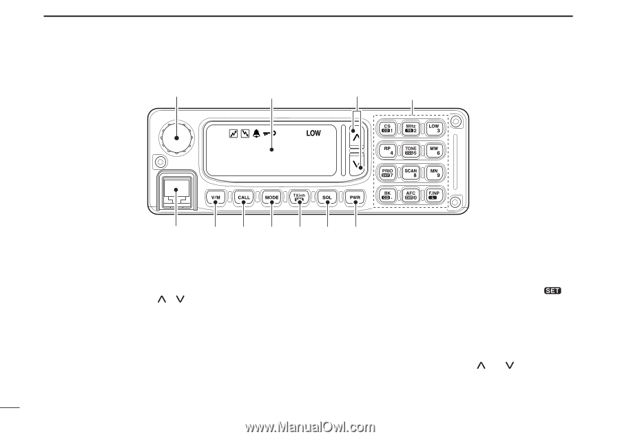
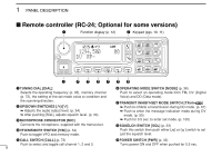
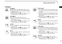
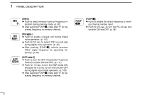
1 PANEL DESCRIPTION Remote controller (RC-24; Optional for some versions) q Function display (p. 12) w Keypad (pgs. 10, 11) 1294.500 00 DV RP- e rtyuio q TUNING DIAL [DIAL] Selects the operating frequency (p. 35), memory channel (p. 72), the setting of the set mode value or condition and the scanning direction. w UP/DOWN SWITCHES Adjusts the audio output level. (p. 34) ➥ After pushing [SQL], adjusts squelch level. (p. 33) e MICROPHONE CONNECTOR [MIC] Connects the microphone, supplied with the transceiver. r VFO/MEMORY SWITCH [V/M] (p. 34) Push to toggle VFO and memory mode. t CALL SWITCH [CALL] (p. 73) Push to select and toggle call channel 1, 2 and 3. 9 y OPERATING MODE SWITCH [MODE] (p. 38) Push to select an operating mode from FM, DV (Digital Voice) and DD (Data mode). u TRANSMIT INHIBIT•SET MODE SWITCH [TXinh• ] ➥ Push to inhibits a transmission during DD mode. (p. 67) ➥ Push to enter the message indication mode during DV mode. (p. 50) ➥ Push for 0.5 sec. to enter set mode. (p. 100) i SQUELCH SWITCH [SQL] (p. 33) Push this switch then push either [ ] or [ ] switch to adjust the squelch level. o POWER SWITCH [PWR] (p. 33) Turns power ON and OFF when pushed for 0.5 sec.
-
 1
1 -
2
-
3
-
4
-
5
-
6
-
7
-
8
-
9
-
10
-
 11
11 -
 12
12 -
 13
13 -
 14
14 -
 15
15 -
 16
16 -
 17
17 -
 18
18 -
 19
19 -
 20
20 -
 21
21 -
22
-
23
-
24
-
25
-
26
-
27
-
28
-
29
-
30
-
31
-
32
-
33
-
34
-
35
-
36
-
37
-
38
-
39
-
40
-
41
-
42
-
43
-
44
-
45
-
46
-
47
-
48
-
49
-
50
-
51
-
52
-
53
-
54
-
55
-
56
-
57
-
58
-
59
-
60
-
61
-
62
-
63
-
64
-
65
-
66
-
67
-
68
-
69
-
70
-
71
-
72
-
73
-
74
-
75
-
76
-
77
-
78
-
79
-
80
-
81
-
82
-
83
-
84
-
85
-
86
-
87
-
88
-
89
-
90
-
91
-
92
-
93
-
94
-
95
-
96
-
97
-
98
-
99
-
100
-
101
-
102
-
103
-
104
-
105
-
106
-
107
-
108
-
109
-
110
-
111
-
112
-
113
-
114
-
115
-
116
-
117
-
118
-
119
-
120
-
121
-
122
-
123
-
124
 |
 |