Icom ID-1 Instruction Manual - Page 8
Panel Description - digital connection
 |
View all Icom ID-1 manuals
Add to My Manuals
Save this manual to your list of manuals |
Page 8 highlights
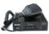
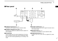
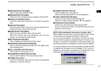
1 PANEL DESCRIPTION Front panel DIGITAL TRANSCEIVER ID-1 MIC TD/RD PWR TX/RX POWER q wer t q MICROPHONE CONNECTOR [MIC] Connects the supplied microphone or the remote controller, RC-24 (optional for some versions). q i Front panel view q +8 V DC output (Max. 100 mA) w Channel up/down e Data out r PTT t GND (microphone ground) y MIC (microphone input) u GND i Data IN w DATA TRANSMIT/RECEIVE INDICATOR Lights green while receiving; lights red while transmitting data in data mode. e POWER INDICATOR Lights while the transceiver power is turned ON. r TRANSMIT/RECEIVE INDICATOR Lights green while receiving; lights red while transmitting in FM/digital voice mode. t POWER SWITCH [POWER] Turns power ON and OFF when pushed for 1 sec. 1
-
 1
1 -
2
-
 3
3 -
 4
4 -
 5
5 -
 6
6 -
 7
7 -
 8
8 -
 9
9 -
 10
10 -
 11
11 -
 12
12 -
 13
13 -
14
-
15
-
16
-
17
-
18
-
19
-
20
-
21
-
22
-
23
-
24
-
25
-
26
-
27
-
28
-
29
-
30
-
31
-
32
-
33
-
34
-
35
-
36
-
37
-
38
-
39
-
40
-
41
-
42
-
43
-
44
-
45
-
46
-
47
-
48
-
49
-
50
-
51
-
52
-
53
-
54
-
55
-
56
-
57
-
58
-
59
-
60
-
61
-
62
-
63
-
64
-
65
-
66
-
67
-
68
-
69
-
70
-
71
-
72
-
73
-
74
-
75
-
76
-
77
-
78
-
79
-
80
-
81
-
82
-
83
-
84
-
85
-
86
-
87
-
88
-
89
-
90
-
91
-
92
-
93
-
94
-
95
-
96
-
97
-
98
-
99
-
100
-
101
-
102
-
103
-
104
-
105
-
106
-
107
-
108
-
109
-
110
-
111
-
112
-
113
-
114
-
115
-
116
-
117
-
118
-
119
-
120
-
121
-
122
-
123
-
124
 |
 |

■
Front panel
q
MICROPHONE CONNECTOR [MIC]
Connects the supplied microphone or the remote con-
troller, RC-24 (optional for some versions).
q
+8 V DC output (Max. 100 mA)
w
Channel up/down
e
Data out
r
PTT
t
GND (microphone ground)
y
MIC (microphone input)
u
GND
i
Data IN
w
DATA TRANSMIT/RECEIVE INDICATOR
Lights green while receiving; lights red while transmitting
data in data mode.
e
POWER INDICATOR
Lights while the transceiver power is turned ON.
r
TRANSMIT/RECEIVE INDICATOR
Lights green while receiving; lights red while transmitting
in FM/digital voice mode.
t
POWER SWITCH [POWER]
Turns power ON and OFF when pushed for 1 sec.
q
i
Front panel view
MIC
TD/RD
PWR
TX/RX
POWER
TRANSCEIVER
ID-1
DIGITAL
q
e
w
r
t
1
PANEL DESCRIPTION
1