Icom ID-1 Instruction Manual - Page 79
Call channel selection
 |
View all Icom ID-1 manuals
Add to My Manuals
Save this manual to your list of manuals |
Page 79 highlights
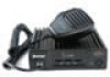
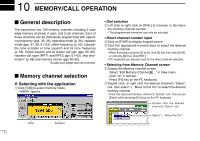
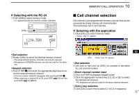
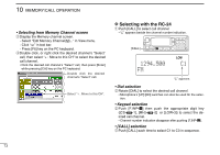
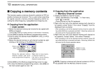
MEMORY/CALL OPERATION 10 D Selecting with the RC-24 q Push [V/M] to select memory mode. • "M" appears beside the channel number indication. [V/M] 1294.500 FM LOW M00 Appears • Dial selection w Rotate [DIAL] to select the desired memory channel. • The programmed memory channels can only be selected. • Microphone's [UP]/[DN] switches can also be used for the selec- tion. • Keypad selection wPush [F.INP•L] then push the appropriate digit keys to se- lect the desired memory channel. • Channel number indication disappear after pushing [F.INP•L]. • When selecting a channel 00 to 09, push [AFC• •0] first then push [AFC• •0]-[MN•9]. Call channel selection Call channel is pre-programmed memory channel that can be accessed by simply clicking call channel button. The transceiver has 3 call channels. D Selecting with the application q Click [CALL] to select memory mode. • "CALL" and "C" appear. 10 Click "CALL" and "C" appear. • Dial selection wLeft click or right click on [DIAL] to increase or decrease the call channel number. • Direct channel number input w Click on [F.INP] to displays keypad screen. eClick the appropriate numeral key ([1], [2] or [3]) to select the desired call channel. • PC keyboard can also be used for the direct channel selection. • [CALL] key selection w Click [CALL] each time to select C1 to C3 in sequence. 72
-
 1
1 -
2
-
3
-
4
-
5
-
6
-
7
-
8
-
9
-
10
-
11
-
12
-
13
-
14
-
15
-
16
-
17
-
18
-
19
-
20
-
21
-
22
-
23
-
24
-
25
-
26
-
27
-
28
-
29
-
30
-
31
-
32
-
33
-
34
-
35
-
36
-
37
-
38
-
39
-
40
-
41
-
42
-
43
-
44
-
45
-
46
-
47
-
48
-
49
-
50
-
51
-
52
-
53
-
54
-
55
-
56
-
57
-
58
-
59
-
60
-
61
-
62
-
63
-
64
-
65
-
66
-
67
-
68
-
69
-
70
-
71
-
72
-
73
-
 74
74 -
 75
75 -
 76
76 -
 77
77 -
 78
78 -
 79
79 -
 80
80 -
 81
81 -
 82
82 -
 83
83 -
 84
84 -
85
-
86
-
87
-
88
-
89
-
90
-
91
-
92
-
93
-
94
-
95
-
96
-
97
-
98
-
99
-
100
-
101
-
102
-
103
-
104
-
105
-
106
-
107
-
108
-
109
-
110
-
111
-
112
-
113
-
114
-
115
-
116
-
117
-
118
-
119
-
120
-
121
-
122
-
123
-
124
 |
 |