Icom ID-1 Instruction Manual - Page 20
Installation And Connections - radio
 |
View all Icom ID-1 manuals
Add to My Manuals
Save this manual to your list of manuals |
Page 20 highlights
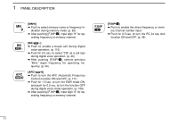
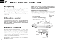
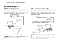
2 INSTALLATION AND CONNECTIONS Unpacking After unpacking, immediately report any damage to the delivering carrier or dealer. Keep the shipping cartons. For a description and a diagram of accessory equipment included with the ID-1, see 'Supplied Accessories' on p. iv of this manual. Selecting a location Select a location for the transceiver that allows adequate air circulation, free from extreme heat, cold, or vibrations, and away from TV sets, TV antenna elements, radios and other electromagnetic sources. NOTE: There are many publications covering proper antennas and their installation. Check with your local dealer for more information and recommendations. • Antenna location for mobile operation To obtain maximum performance from the transceiver, select a high-quality antenna and mount it in a good location. A nonradial antenna should be used when using a magnetic mount. Roof-mount antenna (Drill a hole or use a magnetic mount.) Trunk-mount antenna Gutter-mount antenna Antenna connection For radio communications, the antenna is of critical importance, along with output power and sensitivity. Select antenna(s), such as a well-matched 50 Ω antenna, and feedline. 1.5:1 or better of Voltage Standing Wave Ratio (VSWR) is recommended for your desired band. Of course, the transmission line should be a coaxial cable. CAUTION: Protect your transceiver from lightning by using a lightning arrestor. 13 ID-1 To antenna
-
 1
1 -
2
-
3
-
4
-
5
-
6
-
7
-
8
-
9
-
10
-
11
-
12
-
13
-
14
-
 15
15 -
 16
16 -
 17
17 -
 18
18 -
 19
19 -
 20
20 -
 21
21 -
 22
22 -
 23
23 -
 24
24 -
 25
25 -
26
-
27
-
28
-
29
-
30
-
31
-
32
-
33
-
34
-
35
-
36
-
37
-
38
-
39
-
40
-
41
-
42
-
43
-
44
-
45
-
46
-
47
-
48
-
49
-
50
-
51
-
52
-
53
-
54
-
55
-
56
-
57
-
58
-
59
-
60
-
61
-
62
-
63
-
64
-
65
-
66
-
67
-
68
-
69
-
70
-
71
-
72
-
73
-
74
-
75
-
76
-
77
-
78
-
79
-
80
-
81
-
82
-
83
-
84
-
85
-
86
-
87
-
88
-
89
-
90
-
91
-
92
-
93
-
94
-
95
-
96
-
97
-
98
-
99
-
100
-
101
-
102
-
103
-
104
-
105
-
106
-
107
-
108
-
109
-
110
-
111
-
112
-
113
-
114
-
115
-
116
-
117
-
118
-
119
-
120
-
121
-
122
-
123
-
124
 |
 |
