Canon PIXMA MP500 MP500 User's Guide - Page 17
Rear View and Interior - paper jam
 |
View all Canon PIXMA MP500 manuals
Add to My Manuals
Save this manual to your list of manuals |
Page 17 highlights
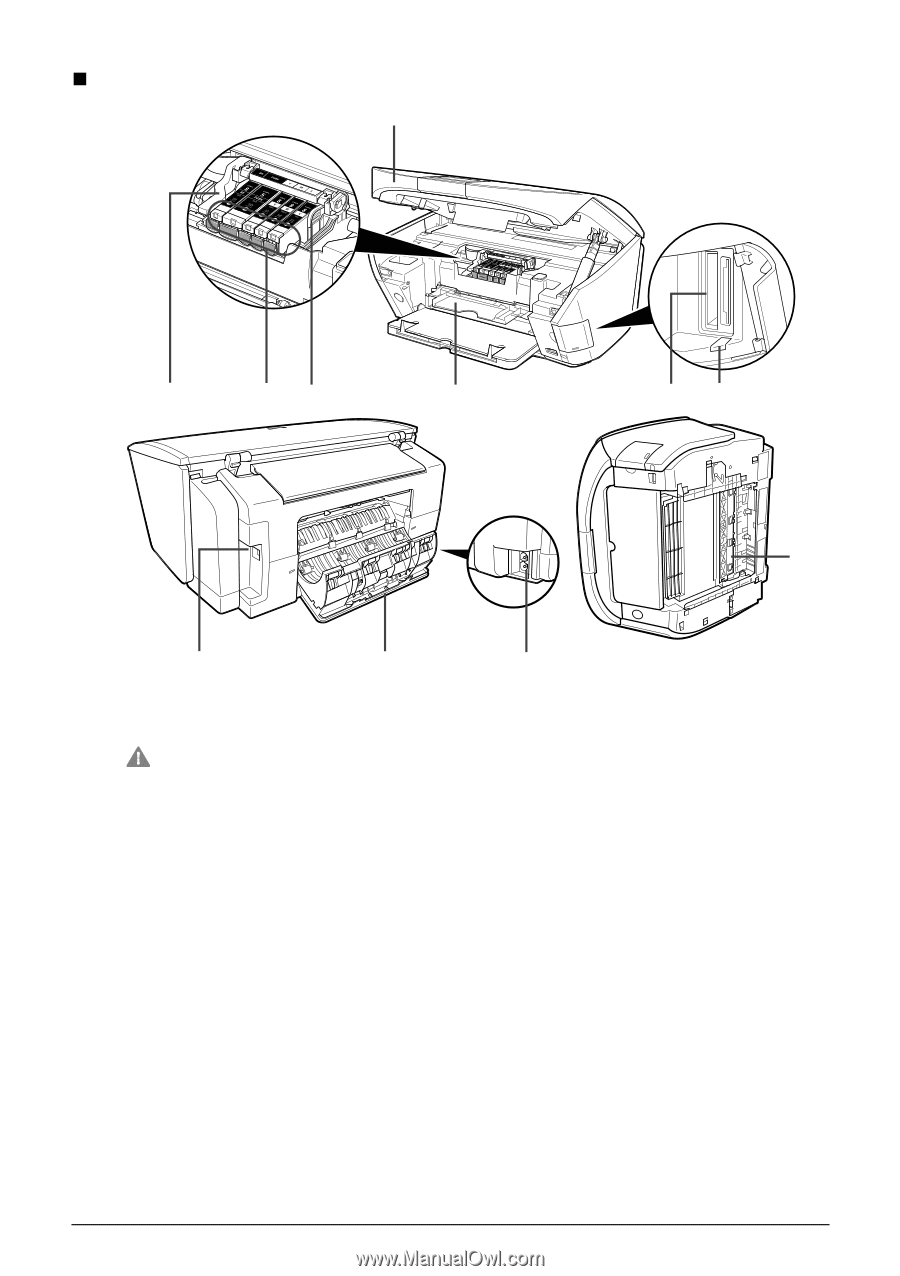
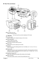
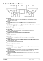
„ Rear View and Interior (17) (14) (15) (16) (18) (19) (20) (21) (24) (23) (22) (14) Print Head Lock Lever Used to fix the Print Head. Important Do not pull up this lever after installing the Print Head. (15) Ink Tank Lamp Lights or flashes red to indicate the status of the ink tank. (16) Print Head Holder Used to install a Print Head. (17) Scanning Unit (Printer Cover) This is the unit used to scan documents. (18) Inner Cover Open this cover when replacing the ink tanks. (19) Card Slot Set the memory card containing photos here. For details, see "Inserting the Memory Card" on page 49. (20) Access Lamp Lights when a memory card is inserted into the Card Slot. This lamp flashes while the machine is reading or writing data from/to the memory card. For details, see "Inserting the Memory Card" on page 49. (21) Duplexing Transport Unit Open when clearing jammed paper after pulling out the Cassette. (22) Power Connector This is the connector used to connect the provided power cord. Chapter 1 Before Printing 15
-
 1
1 -
2
-
3
-
4
-
5
-
6
-
7
-
8
-
9
-
10
-
11
-
 12
12 -
 13
13 -
 14
14 -
 15
15 -
 16
16 -
 17
17 -
 18
18 -
 19
19 -
 20
20 -
 21
21 -
 22
22 -
23
-
24
-
25
-
26
-
27
-
28
-
29
-
30
-
31
-
32
-
33
-
34
-
35
-
36
-
37
-
38
-
39
-
40
-
41
-
42
-
43
-
44
-
45
-
46
-
47
-
48
-
49
-
50
-
51
-
52
-
53
-
54
-
55
-
56
-
57
-
58
-
59
-
60
-
61
-
62
-
63
-
64
-
65
-
66
-
67
-
68
-
69
-
70
-
71
-
72
-
73
-
74
-
75
-
76
-
77
-
78
-
79
-
80
-
81
-
82
-
83
-
84
-
85
-
86
-
87
-
88
-
89
-
90
-
91
-
92
-
93
-
94
-
95
-
96
-
97
-
98
-
99
-
100
-
101
-
102
-
103
-
104
-
105
-
106
-
107
-
108
-
109
-
110
-
111
-
112
-
113
-
114
-
115
-
116
-
117
-
118
-
119
-
120
-
121
-
122
-
123
-
124
-
125
-
126
-
127
-
128
-
129
-
130
-
131
-
132
-
133
-
134
-
135
-
136
-
137
-
138
-
139
-
140
-
141
-
142
-
143
-
144
-
145
-
146
-
147
-
148
-
149
-
150
-
151
-
152
-
153
-
154
-
155
-
156
 |
 |