Dell PowerConnect J-SRX100 Hardware Guide - Page 24
J-SRX100 Services Gateway Back Panel, J-SRX100 Services Gateway Built-In Interfaces
 |
View all Dell PowerConnect J-SRX100 manuals
Add to My Manuals
Save this manual to your list of manuals |
Page 24 highlights
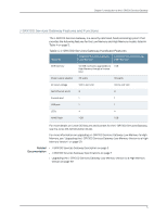
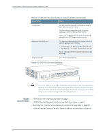
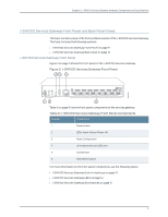
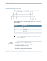
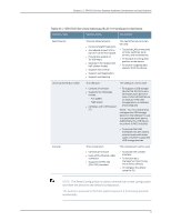
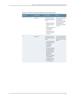
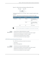
PowerConnect J-SRX100 Services Gateway Hardware Guide J-SRX100 Services Gateway Back Panel Figure 3 on page 10 illustrates the back panel of the J-SRX100 Services Gateway. Figure 3: J-SRX100 Services Gateway Back Panel Table 7 on page 10 lists the components available on the back panel of the J-SRX100 Services Gateway. Table 7: J-SRX100 Services Gateway Back Panel Number Component 1 Lock 2 Grounding point 3 Cable tie holder 4 Power supply point NOTE: The cable tie holder provides support for holding the power cord on the power supply point. The lock provides the option to lock and secure the device to the installation site. Related • J-SRX100 Services Gateway Specifications on page 7 Documentation • J-SRX100 Services Gateway Built-In Interfaces on page 10 • J-SRX100 Services Gateway LEDs on page 12 • J-SRX100 Services Gateway Boot Devices on page 15 • J-SRX100 Services Gateway Power Supply on page 16 J-SRX100 Services Gateway Built-In Interfaces Table 8 on page 11 summarizes the interface ports supported on the J-SRX100 Services Gateway. 10
-
 1
1 -
2
-
3
-
4
-
5
-
6
-
7
-
8
-
9
-
10
-
11
-
12
-
13
-
14
-
15
-
16
-
17
-
18
-
 19
19 -
 20
20 -
 21
21 -
 22
22 -
 23
23 -
 24
24 -
 25
25 -
 26
26 -
 27
27 -
 28
28 -
 29
29 -
30
-
31
-
32
-
33
-
34
-
35
-
36
-
37
-
38
-
39
-
40
-
41
-
42
-
43
-
44
-
45
-
46
-
47
-
48
-
49
-
50
-
51
-
52
-
53
-
54
-
55
-
56
-
57
-
58
-
59
-
60
-
61
-
62
-
63
-
64
-
65
-
66
-
67
-
68
-
69
-
70
-
71
-
72
-
73
-
74
-
75
-
76
-
77
-
78
-
79
-
80
-
81
-
82
-
83
-
84
-
85
-
86
-
87
-
88
-
89
-
90
-
91
-
92
-
93
-
94
-
95
-
96
-
97
-
98
-
99
-
100
-
101
-
102
-
103
-
104
-
105
-
106
-
107
-
108
-
109
-
110
-
111
-
112
-
113
-
114
-
115
-
116
-
117
-
118
-
119
-
120
-
121
-
122
-
123
-
124
-
125
-
126
-
127
-
128
-
129
-
130
-
131
-
132
-
133
-
134
-
135
-
136
-
137
-
138
-
139
-
140
-
141
-
142
-
143
-
144
-
145
-
146
-
147
-
148
-
149
-
150
-
151
-
152
-
153
-
154
-
155
-
156
-
157
-
158
 |
 |